A snap-on button correction tool and correction method

A snap-on, button technology, applied in electrical components, electrical switches, circuits, etc., can solve problems such as poor hand feel, and achieve the effect of avoiding the deviation of the button position and improving the pressing feel

Active Publication Date: 2018-11-27
GEER TECH CO LTD
View PDF6 Cites 0 Cited by
  • Summary
  • Abstract
  • Description
  • Claims
  • Application Information

AI Technical Summary

Problems solved by technology

[0004] In view of the problem of poor hand feeling caused by snap-on buttons in the prior art due to incomplete return during the assembly process, a snap-on button correction tool and correction method of the present invention is proposed in order to overcome the above problems or at least partially solve them above question

Method used


Image

  • A snap-on button correction tool and correction method
  • A snap-on button correction tool and correction method
  • A snap-on button correction tool and correction method

Examples


Embodiment Construction

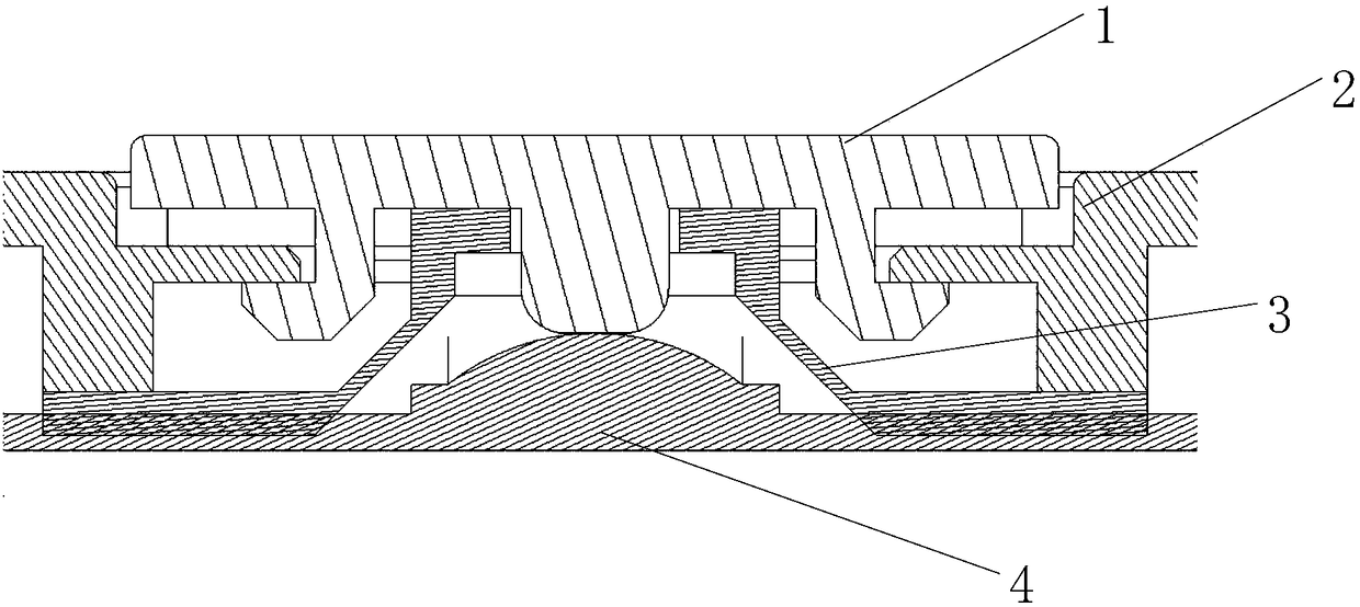
[0021] In order to solve the problem that the key does not return in place during the key assembly process, the invention provides a buckle-type key correction tool. After the key is assembled, the key is squeezed from the inside of the shell by the correction tool to ensure that the key rebounds in place, effectively Improved button feel after assembly. In order to make the object, technical solution and advantages of the present invention clearer, the embodiments of the present invention will be further described in detail below in conjunction with the accompanying drawings.

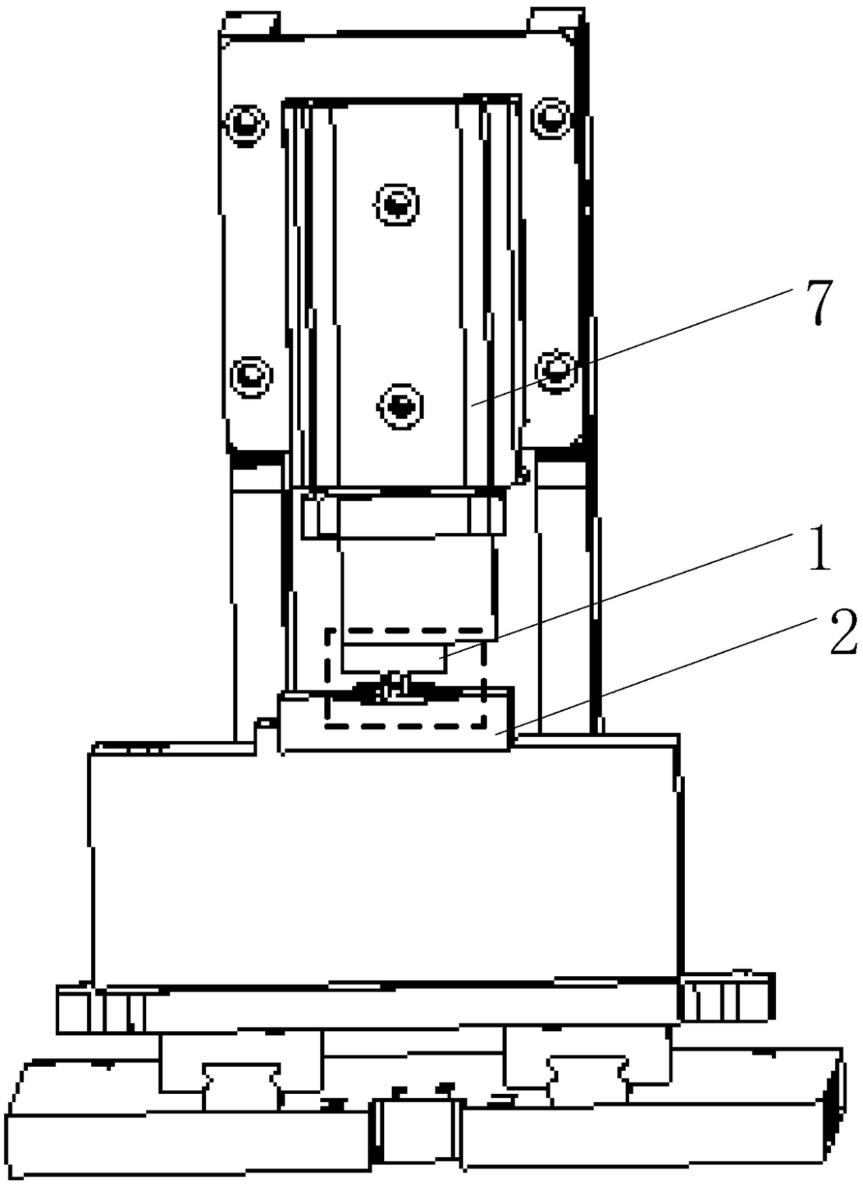
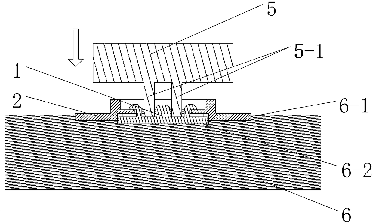
[0022] figure 2 A schematic diagram of a buckle-type button correction tool provided by an embodiment of the present invention; image 3 for figure 2 The cross-sectional view of the part indicated by the dotted frame of the snap-on button correction tool shown. Such as figure 2 and image 3 As shown, the buckle-type button correction tooling includes an upper pressing device 5 and a lower profi...


PUM


Abstract

The invention discloses a buckle type key correcting tool and a correcting method. The correcting tool comprises an upper pressurizing device and a lower copying device; a pressing rod is arranged on the lower side of the upper pressurizing device; a copying groove is formed in the lower copying device and is used for inverting a shell with a key; preset height is reserved between the bottom of the copying groove and the key; and when the upper pressurizing device presses down, the pressing rod is driven to press the key to correct the state of the key. The key is pressed from the inner side of the shell by the upper pressurizing device to move downwards relative to the shell to return to be corrected in position, so that the key can be guaranteed to return in place after being assembled, key position deviation caused by the fact that the buckle of the key does not return in place or plastic is deformed after assembling is avoided, and the pressing hand feeling of the buckle type key after assembling is improved.

Description

technical field [0001] The invention relates to the technical field of button assembly, in particular to a buckle-type button correction tool and a correction method. Background technique [0002] The snap button is a button form commonly used in consumer electronics products. figure 1 It is a structural schematic diagram of a buckle button. The button 1 is inserted into the shell 2 through the deformation of the buckle. When the assembly is completed, a rubber gasket 3 is arranged between the button 1 and the shell 2, and the pillar top on the lower side of the button 1 On the dome sheet 4, the button feel is provided by the dome sheet 4. [0003] However, during the assembly process, since the button 1 is stuck into the shell 2 by the deformation of the plastic buckle, the button may not return in place due to the buckle or the deformation of the plastic, resulting in the position of the button 1 being misaligned. Slanting, friction with the shell 2, etc., affect the reb...

Claims


Application Information

Patent Timeline
Patent Type & Authority Patents(China)
IPC IPC(8): H01H11/00
CPCH01H11/00H01H2011/0075
Inventor 郭宁
Owner GEER TECH CO LTD
Why Eureka
Try Eureka