
Movement mechanism of separation plate in drawer seat of drawer type circuit breaker

A drawer-type circuit breaker and motion mechanism technology, applied in the direction of pull-out switch cabinets, switchgear, electrical components, etc., can solve the problems of insufficient movement speed and insufficient movement stability of the safety isolation door, so as to achieve rapid opening action and movement. The process is smooth and the effect of ensuring the reliable performance of the action

Active Publication Date: 2017-05-31
SHANGHAI RENMIN ELECTRICAL APP WORKS
View PDF5 Cites 2 Cited by
  • Summary
  • Abstract
  • Description
  • Claims
  • Application Information

AI Technical Summary

Problems solved by technology

[0005] The purpose of the present invention is to provide a movement mechanism for the isolation plate in the drawer seat of a drawer circuit breaker to solve the problems of insufficient movement stability and rapid action of the safety isolation door in the drawer seat of the existing frame circuit breaker

Method used


Image

  • Movement mechanism of separation plate in drawer seat of drawer type circuit breaker
  • Movement mechanism of separation plate in drawer seat of drawer type circuit breaker
  • Movement mechanism of separation plate in drawer seat of drawer type circuit breaker

Examples


Embodiment

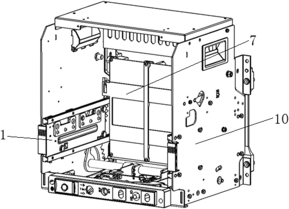
[0035] The structure of the drawer seat of the drawer circuit breaker is as follows: figure 1 As shown, the drawer seat includes the drawer seat side plates 10 on the left and right sides, and a casing, and a separation plate 7 is arranged in the casing.

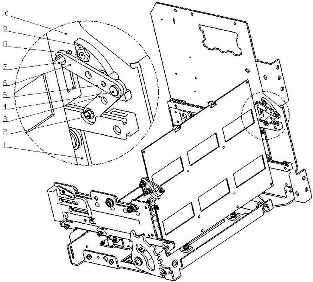
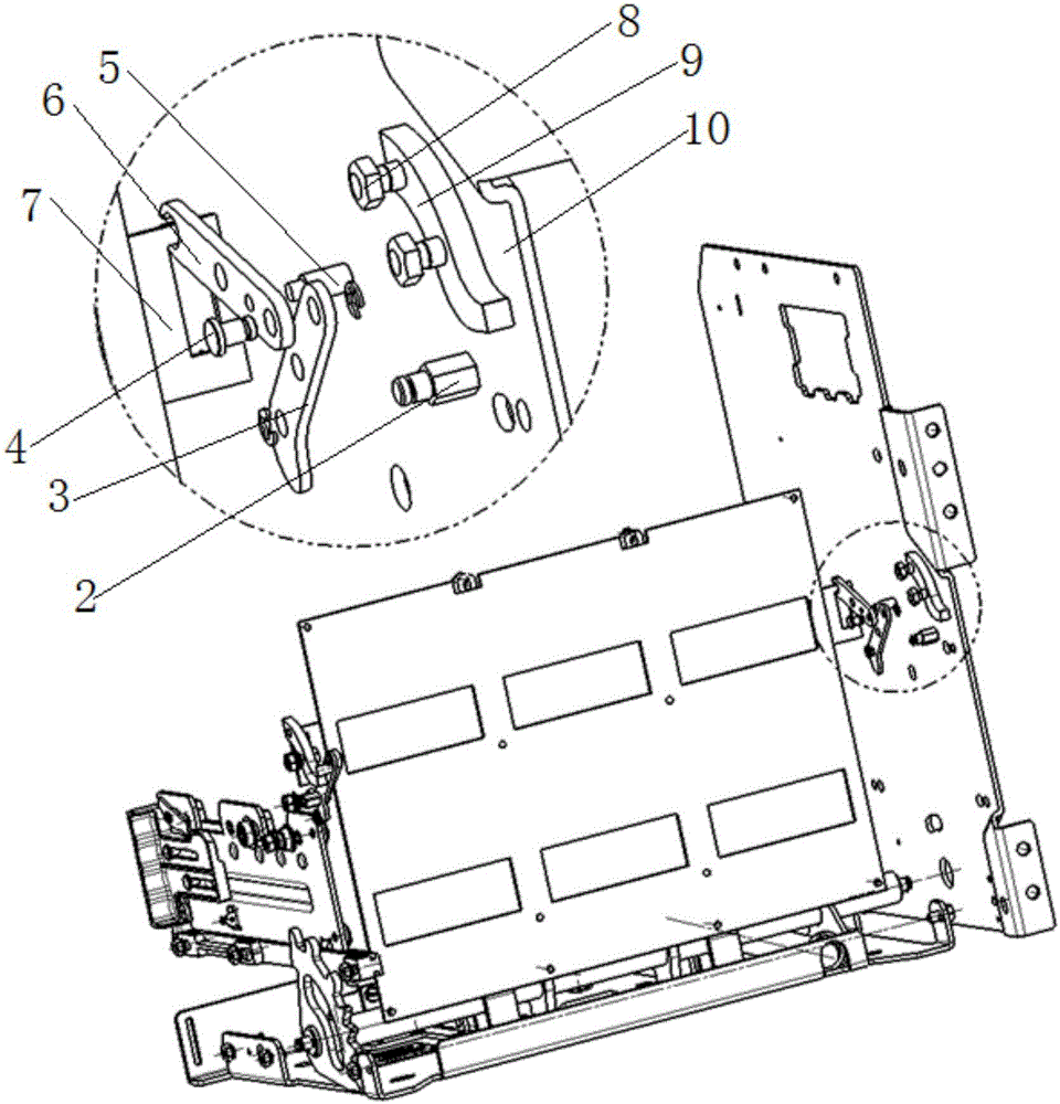
[0036] This embodiment provides a movement mechanism for the isolation plate in the drawer seat of a drawer type circuit breaker, such as figure 2 , image 3 , Figure 4 As shown, the moving mechanism of the isolation plate includes an upper link 6, a lower link 3, a sliding shaft 5, a guide rail 9 and a moving side plate 1, the isolation plate 7 is perpendicular to the side plate 10 of the drawer seat, and the lower link 3 is rotatably connected to the drawer seat On the side plate 10, the upper end of the upper connecting rod 6 is connected with the isolation plate 7, the lower end is hinged with the lower connecting rod 3, the sliding shaft 5 is arranged on the upper connecting rod 6, the guide rail 9 is fixed on the s...


PUM


Abstract

The invention relates to a movement mechanism of a separation plate in a drawer seat of a drawer type circuit breaker. The mechanism comprises an upper connecting rod, a lower connecting rod, a sliding shaft, a guide rail and a movement side plate, wherein the lower connecting rod is rotatably connected with a side plate of the drawer seat; the upper end of the upper connecting rod is connected with the separation plate and the lower end of the upper connecting rod is hinged to the lower connecting rod; the sliding shaft is arranged on the upper connecting rod and the guide rail is arranged on the side plate of the drawer seat; the guide rail is used as a movement limiting rail of the sliding shaft, so that when the upper connecting rod moves, the vertex at the upper end of the upper connecting rod moves up and down; the movement side plate is parallel to the side plate of the drawer seat; in a horizontal sliding process of the movement side plate, the lower connecting rod is pushed to rotate, so that the upper connecting rod is driven to move; the movement of the upper connecting rod drives the separation plate to move up and down. Compared with the prior art, the upper connecting rod and the lower connecting rod are hinged, a clamping condition does not occur and the stability is high; compared with other mechanisms, door opening movement is more rapid. The movement angle of the connecting rods is limited by the shapes of the connecting rods, so that the mechanism does not pass through a dead point, and the reliability performance of movement is ensured.

Description

technical field [0001] The invention belongs to the technical field of electrical appliances, and in particular relates to a moving mechanism of an isolation plate in a drawer seat of a drawer-type circuit breaker. Background technique [0002] Universal circuit breaker, also known as frame circuit breaker, can connect, carry and break current under normal circuit conditions, and can also break fault current under specified abnormal circuit conditions. As far as the application of universal circuit breaker is concerned, it is divided into fixed circuit breaker and drawer circuit breaker. Because the drawer circuit breaker is installed in the drawer and can be moved in the drawer, it has the advantages of convenient detection and maintenance, so it is widely used. use. [0003] The drawer type circuit breaker is composed of two parts: the circuit breaker body and the drawer type socket. During use, the electrical circuit can be disconnected by the main contact of the circuit...

Claims


Application Information

Patent Timeline
IPC IPC(8): H02B11/127
CPCH02B11/127
Inventor 何亚伟眭皓徐琛君
Owner SHANGHAI RENMIN ELECTRICAL APP WORKS
Learn More