Bionic direct-drive mechanism based on resonance system

A technology of direct drive and DC motor, applied in the direction of manipulators, micro manipulators, manufacturing tools, etc., can solve the problems of structural vibration and asymmetrical inertial force, motion trajectory can not be fully controllable, and limit the freedom of limb movement. Achieve the effect of solving energy dissipation, simple structure and high reliability

Pending Publication Date: 2022-04-12
BEIHANG UNIV
View PDF6 Cites 0 Cited by
  • Summary
  • Abstract
  • Description
  • Claims
  • Application Information

AI Technical Summary

Problems solved by technology

[0004] The existing motor plus mechanical structure drive method has the following defects: (1) In order to convert rotation into reciprocating motion, the structure and production are often more complicated, and the vibration and asymmetric inertial force generated by the structure under high-speed motion are relatively large
(2) The mechanical structure will also have a certain power loss during the transmission process
(3) The fixed mechanical transmission also limits the freedom of movement of the limbs, and the trajectory of the movement cannot be completely controlled like a living thing, requiring additional control force

Method used


Image

  • Bionic direct-drive mechanism based on resonance system
  • Bionic direct-drive mechanism based on resonance system
  • Bionic direct-drive mechanism based on resonance system

Examples


Embodiment Construction

[0038] In order to more clearly understand the above objects, features and advantages of the present invention, the present invention will be further described in detail below in conjunction with the accompanying drawings and specific embodiments. It should be noted that, in the case of no conflict, the embodiments of the present invention and the features in the embodiments can be combined with each other.

[0039] In the following description, many specific details are set forth in order to fully understand the present invention. However, the present invention can also be implemented in other ways different from those described here. Therefore, the protection scope of the present invention is not limited by the specific details disclosed below. EXAMPLE LIMITATIONS.

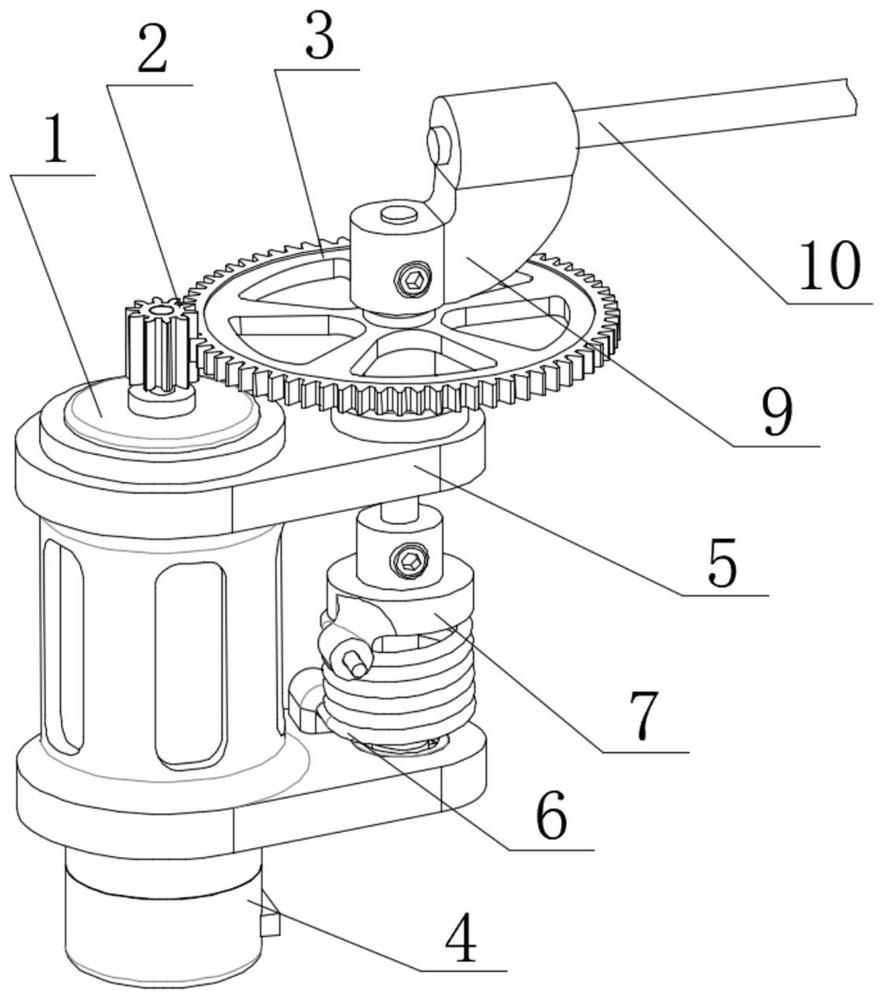
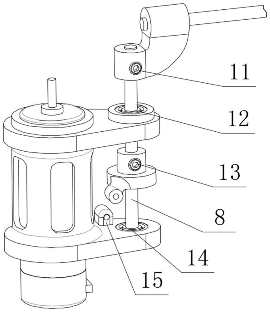
[0040] figure 1 It is a schematic diagram of a bionic direct drive mechanism based on a resonance system of the present invention, figure 2 It is a schematic diagram of the mechanism for removing gears and to...


PUM


Abstract

The bionic direct-drive mechanism based on the resonance system comprises a machine body frame, a direct-current motor, an angle sensor, a speed reducing mechanism, an elastic unit and limbs, and the direct-current motor is fixed to the machine body frame; the angle sensor is connected with one end of the output shaft of the direct-current motor and used for measuring the rotation angle and angular velocity of the output shaft of the direct-current motor and feeding back to the motor controller; an input shaft of the reducing mechanism is connected with the other end of the output shaft of the direct-current motor, and an output shaft of the reducing mechanism is connected with limbs to drive the limbs to reciprocate; one end of the elastic element is connected with the output shaft of the reducing mechanism; the elastic element generates stretching or compression deformation when the output end of the speed reducing mechanism rotates, and kinetic energy of inertial motion during reciprocating motion of the limbs is stored. The direct-drive mechanism is used for driving limbs of the micro bionic robot to reciprocate, the motion trail is not limited by mechanical structures such as connecting rods and gears, and the direct-drive mechanism is simple in structure, light in weight, high in driving efficiency and multiple in controlled quantity freedom degree.

Description

technical field [0001] The invention relates to the field of miniature bionic robots, in particular to a bionic direct drive mechanism based on a resonance system. Background technique [0002] In recent years, micro-scale bionic robots have shown great development potential in flexibility, concealment and mobility. Common micro-bionic robots include jumping robots, quadruped robots, flapping-wing aircraft, and fish-shaped robots. There are various driving methods for the motion of this type of bionic robot, but almost all of them generate control force and moment through the reciprocating motion of the limbs. In order to realize this kind of bionic reciprocating trajectory, micro-robots are usually directly driven by piezoelectric, electromagnetic and other methods, or driven by a rotating motor and a connecting rod. [0003] Although piezoelectric drive can generate higher frequencies at higher voltages with lower energy loss, it is only used in millimeter-scale robots. ...

Claims


Application Information

Patent Timeline
Patent Type & Authority Applications(China)
IPC IPC(8): B25J7/00
Inventor 屠展李嵩刘方园王子瑜李道春董鑫
Owner BEIHANG UNIV
Why Eureka
Try Eureka