Robot passive foot with controllable angle and robot using the passive foot

A robot and foot technology, which is applied in the field of robot passive feet, can solve problems such as numerous devices, difficulty in ensuring spring rebound control, and inability to adjust the initial angle between the sole of the foot and the ground, so as to reduce weight and prevent yaw rotation Effect

Active Publication Date: 2021-12-24
BEIJING INSTITUTE OF TECHNOLOGYGY
View PDF18 Cites 0 Cited by
  • Summary
  • Abstract
  • Description
  • Claims
  • Application Information

AI Technical Summary

Problems solved by technology

For example, the Chinese invention patent CN201720399086.9 provides a multi-link flexible bionic foot. The legs and feet are connected by universal joints, and springs are arranged in each direction to achieve the effect of automatic return. The ability to limit the yaw rotation is limited, and the rebound control of the spring is difficult to guarantee; Chinese invention patent 201921091385.1 provides a robot foot with a piston rod as a leg-foot connection, which has strong shock absorption ability and adaptability to rough roads; Chinese invention patent 201911323449.0 provides a flexible robot foot with an elastically expanded arch structure. Its dynamic simulation of the buffering effect of the human foot arch is a highlight. However, the above two inventions have complex structures and a large number of devices, which cannot be applied to lightweight applications. small robot
[0005] The above-mentioned invention patents have strict restrictions on the pitch and swing range of the robot's soles. The position of the robot's feet is fixed after installation, and it is impossible to adjust the initial angle between the soles of the feet and the ground.

Method used


Image

  • Robot passive foot with controllable angle and robot using the passive foot
  • Robot passive foot with controllable angle and robot using the passive foot
  • Robot passive foot with controllable angle and robot using the passive foot

Examples


Embodiment Construction

[0032] In order to make the object, technical solution and advantages of the present invention clearer, the present invention will be further described in detail below in conjunction with the accompanying drawings and embodiments. It should be understood that the specific embodiments described here are only used to explain the present invention, not to limit the present invention.

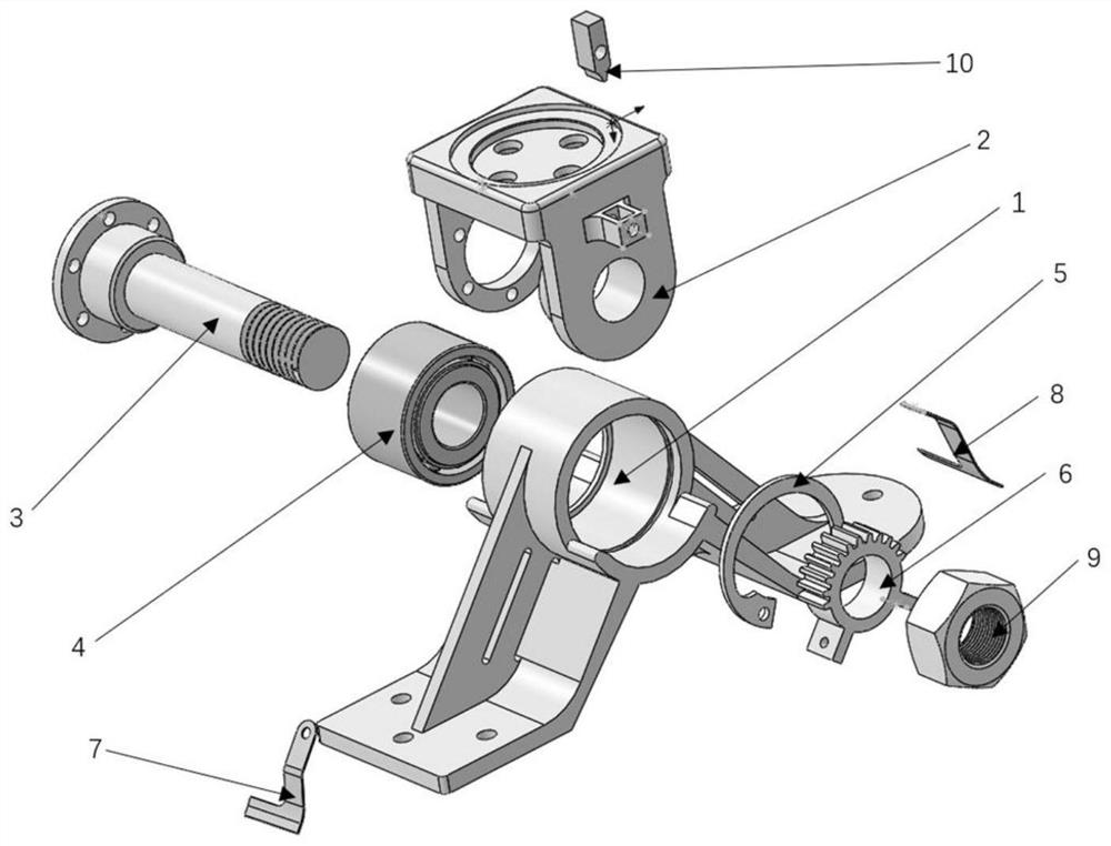
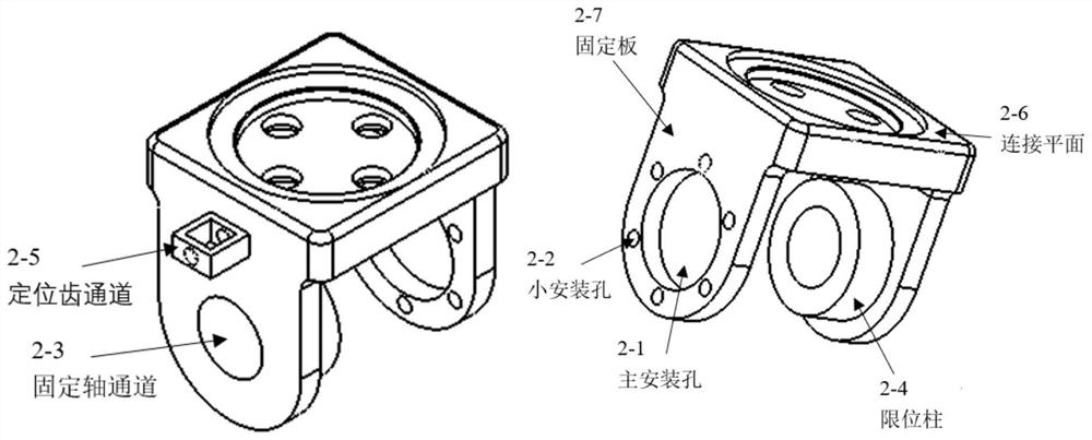
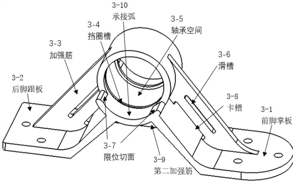
[0033] like figure 1 The shown passive foot of the robot with controllable angle includes a rotating part and a non-rotating part, and the rotating part and the non-rotating part are connected by a spring plate, so as to realize the restriction of the relative movement of the foot body while ensuring the degree of freedom and Automatic return; the rotating part includes a foot body 1 that imitates the bone structure of the human foot arch; the non-rotating part includes a leg-foot connector 2, a fixed shaft 3 and a positioning gear 6; the leg-foot connector 2 is used for Connect the robot leg and ...


PUM


Abstract

The invention discloses a robot passive foot with controllable angle and a robot using the passive foot, including a rotating part and a non-rotating part. Restriction of relative movement of the main body and automatic return; the rotating part includes a foot body that imitates the bone structure of the human foot arch; the non-rotating part includes a leg-foot connector, a fixed shaft and a positioning gear; the leg-foot connector It is used to connect the robot leg and the foot body; the fixed shaft is used to connect the leg-foot connector, the foot body and the positioning gear; the positioning gear is used to adjust the angle between the foot body and the leg-foot connector, And the positioning gear is connected to the main body of the foot through the spring leaf to realize the automatic return of the main body of the foot.

Description

technical field [0001] The invention belongs to the technical field of humanoid robots, and in particular relates to a robot passive foot with controllable angle and a robot using the passive foot. Background technique [0002] The foot of a biped robot is in direct contact with the ground, so it plays a vital role in the stability of the robot. Analogous to human walking, the foot of a robot also has a regularity of rotation when walking, and needs to maintain a certain degree of freedom of rotation. Combined with these characteristics, passively controlled robot feet show a broad application space in the context of the need for lightweight and easy-to-manipulate robots in some application fields. [0003] In general, the human ankle joint can achieve three degrees of freedom of rotation, namely, hook and stretch feet (pitch), external and internal splayed (yaw), and medial and lateral tilt (roll). But in the process of walking, the soles of the feet only have the rotatio...

Claims


Application Information

Patent Timeline
Patent Type & Authority Patents(China)
IPC IPC(8): B62D57/032
CPCB62D57/032
Inventor 陈学超何鹏发韩连强余张国黄强石青
Owner BEIJING INSTITUTE OF TECHNOLOGYGY
Why Eureka
Try Eureka