System for controlling variable geometry equipment of a gas turbine engine especially comprising a guiding track connection

A control system and gas turbine technology, applied in gas turbine installations, engine control, engine components, etc., can solve the problems of increased risk of engine flameout and major disadvantages

Active Publication Date: 2011-08-31
SN DETUDE & DE CONSTR DE MOTEURS DAVIATION S N E C M A
View PDF1 Cites 0 Cited by
  • Summary
  • Abstract
  • Description
  • Claims
  • Application Information

AI Technical Summary

Problems solved by technology

Although the savings achieved by this approach are great (the associated transmission, servo valves, conduits, wiring harnesses, etc. are omitted), the disadvantages are also great, especially at idle, if water or hail enters the engine increases the risk of engine stalling

Method used


Image

  • System for controlling variable geometry equipment of a gas turbine engine especially comprising a guiding track connection
  • System for controlling variable geometry equipment of a gas turbine engine especially comprising a guiding track connection
  • System for controlling variable geometry equipment of a gas turbine engine especially comprising a guiding track connection

Examples


Embodiment Construction

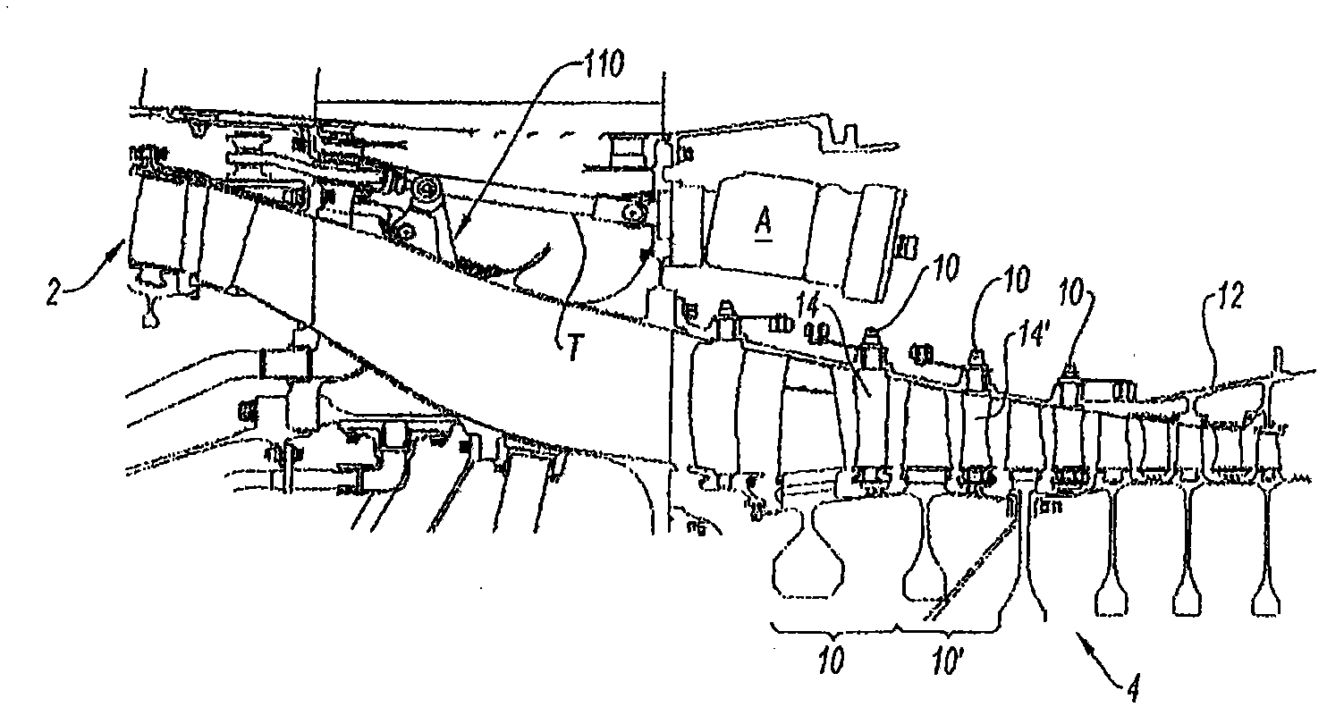
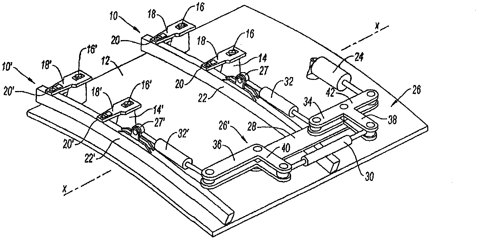
[0054] well known, such as figure 1 with figure 2 As shown, a gas turbine engine suitable for the aerospace field, such as a jet engine (represented here by the X-X axis), includes -- from upstream to downstream --- a fan, a low-pressure compressor 2, a high-pressure compressor 4, a combustor , a high-pressure turbine, a low-pressure turbine and a nozzle (not shown) for injecting gas. The high pressure compressor and the high pressure turbine are firmly fixed to the same shaft, called the high pressure shaft, and thus belong to the high pressure body of the engine or the first body rotating at the first speed, while the low pressure compressor and the low pressure turbine are firmly fixed to the same On the root shaft, called the low-pressure shaft, and therefore belongs to the low-pressure body of the engine or the second body rotating at the second speed.

[0055] In the following, the abbreviations LP and HP denote low pressure and high pressure, respectively.

[0056] ...


PUM


Abstract

The invention relates to a system for controlling at least two sets of variable geometry equipment (10, 110) of a gas turbine engine comprising at least one first body running at a first speed and a second body running at a second speed, the first set of equipment (10) being a stage of variable stator vanes of a compressor of the first body moving between a closed position during idling and an open position at high speed, and the second set of equipment (110) being at least one bleed valve of a compressor of the second body moving between an open position during idling and a closed position at high speed. The system according to the invention is characterised in that it comprises an actuator (24) that actuates the two sets of equipment.

Description

technical field [0001] This invention relates to the general field of variable geometry control of gas turbine engines, especially jet engines. In particular, the invention relates to the optimal control of several devices constituting the different body components of a gas turbine engine. Background technique [0002] The term "variable geometry device" is understood here to mean a device which is connected to a control member and whose size, shape, position and / or speed of rotation can be modified in accordance with detected conditions or determined parameters in order to modify the engine's Work makes a difference. Examples of variable geometry devices include compressor discharge valves (with variable opening), fixed compressor vanes with variable set angles, turbine vanes with variable tip clearance, variable flow fuel pumps, and others. [0003] The term "body" refers to a subassembly of a gas turbine engine, comprising, as main components, the compressor and the tur...

Claims


Application Information

Patent Timeline
Patent Type & Authority Applications(China)
IPC IPC(8): F01D17/16F01D17/20F02C6/08F02C9/18F02C9/22
CPCF02C6/08F01D17/16Y02T50/671F01D17/20F02C9/22F05D2270/58F02C9/18F05B2270/508F04D27/023F04D27/0215F04D27/0246F04D27/0284
Inventor 巴普蒂斯特·贝努特·科洛特布鲁诺·罗伯特·加利
Owner SN DETUDE & DE CONSTR DE MOTEURS DAVIATION S N E C M A
Why Eureka
Try Eureka