A Multi-parameter Joint Inversion Method for Calculating Rock Scattering Attenuation

A technology of scattering attenuation and joint inversion, which is applied in the fields of seismology, seismology, and instruments for logging records, can solve the problems of low sensitivity and difficult scattering attenuation information, etc., and achieve the effect of promoting application and promotion.

Active Publication Date: 2019-08-06
YANGTZE UNIVERSITY
View PDF6 Cites 0 Cited by
  • Summary
  • Abstract
  • Description
  • Claims
  • Application Information

AI Technical Summary

Problems solved by technology

The analysis of the coda attenuation by the single scattered wave model does not distinguish between the intrinsic absorption attenuation and the scattering attenuation, but classifies the two types of attenuation into one item, which is described by "Coda Q". The attenuation of propagating in the medium is equal, ignoring the influence of the energy loss of the direct wave on the attenuation of the wake in the scattering process, it is difficult to truly reflect the scattering attenuation information of the formation (Aki K, Chouet B. Origin of coda waves: Source, attenuation and scattering effects , Journal of Geophysical Research, 1975, 80:3322–3342)
The coda energy flux model assumes that the scattering attenuation and the intrinsic absorption attenuation have different effects on the coda decay rate. As the duration increases, increasing the scattering attenuation will convert more direct wave energy into coda energy, while increasing the intrinsic Absorption attenuation, coda wave and direct wave will lose more elastic energy. This method has low sensitivity of inherent absorption attenuation quality factor at the frequency of several thousand Hz in acoustic logging, and is not suitable for the calculation of scattering attenuation in borehole acoustic logging. (Frankel A, Wennerberg L. Energy-fluxmodel of seismic coda: Separation of scattering and intrinsic attenuation, Bulletin of the Seismological Society America, 1987, 77: 1223-1251)

Method used


Image

  • A Multi-parameter Joint Inversion Method for Calculating Rock Scattering Attenuation
  • A Multi-parameter Joint Inversion Method for Calculating Rock Scattering Attenuation
  • A Multi-parameter Joint Inversion Method for Calculating Rock Scattering Attenuation

Examples


Embodiment Construction

[0027] The present invention will be further described below in conjunction with the accompanying drawings and embodiments. The following examples will help those skilled in the art to further understand the present invention, but do not limit the present invention in any form.

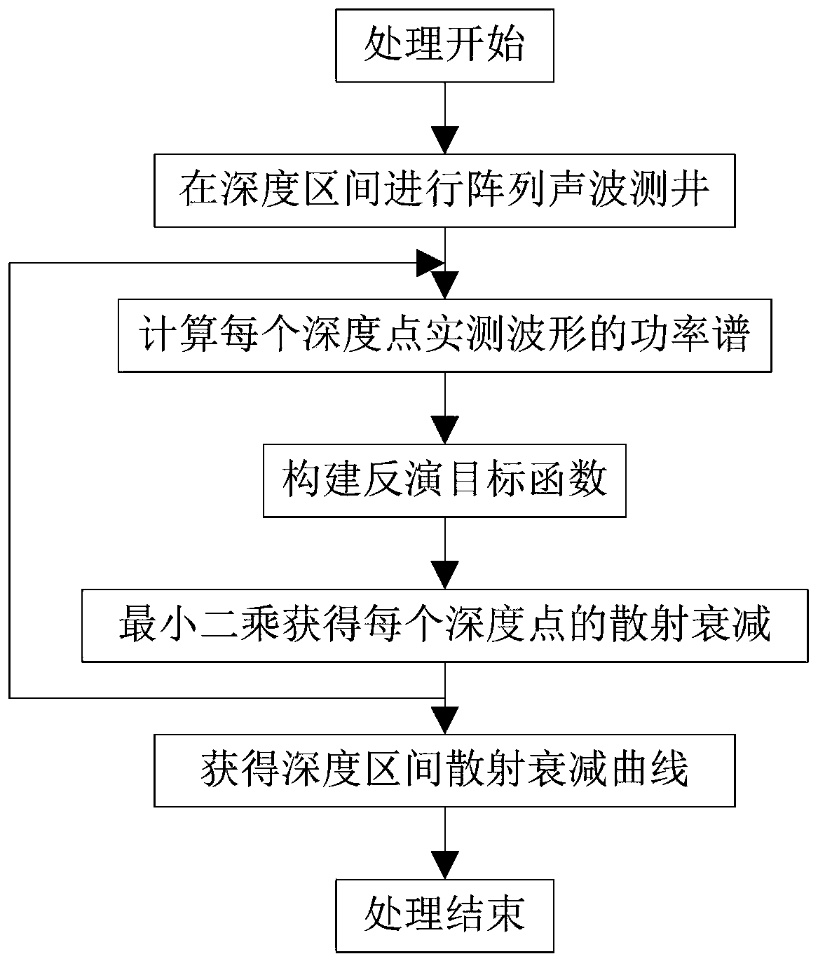
[0028] like figure 1 As shown, the present invention provides a method for multi-parameter joint inversion calculation of rock scattering attenuation, comprising the following steps:

[0029] Step 1: Perform array acoustic logging in the depth interval to obtain dipole array waveform data in the depth interval;

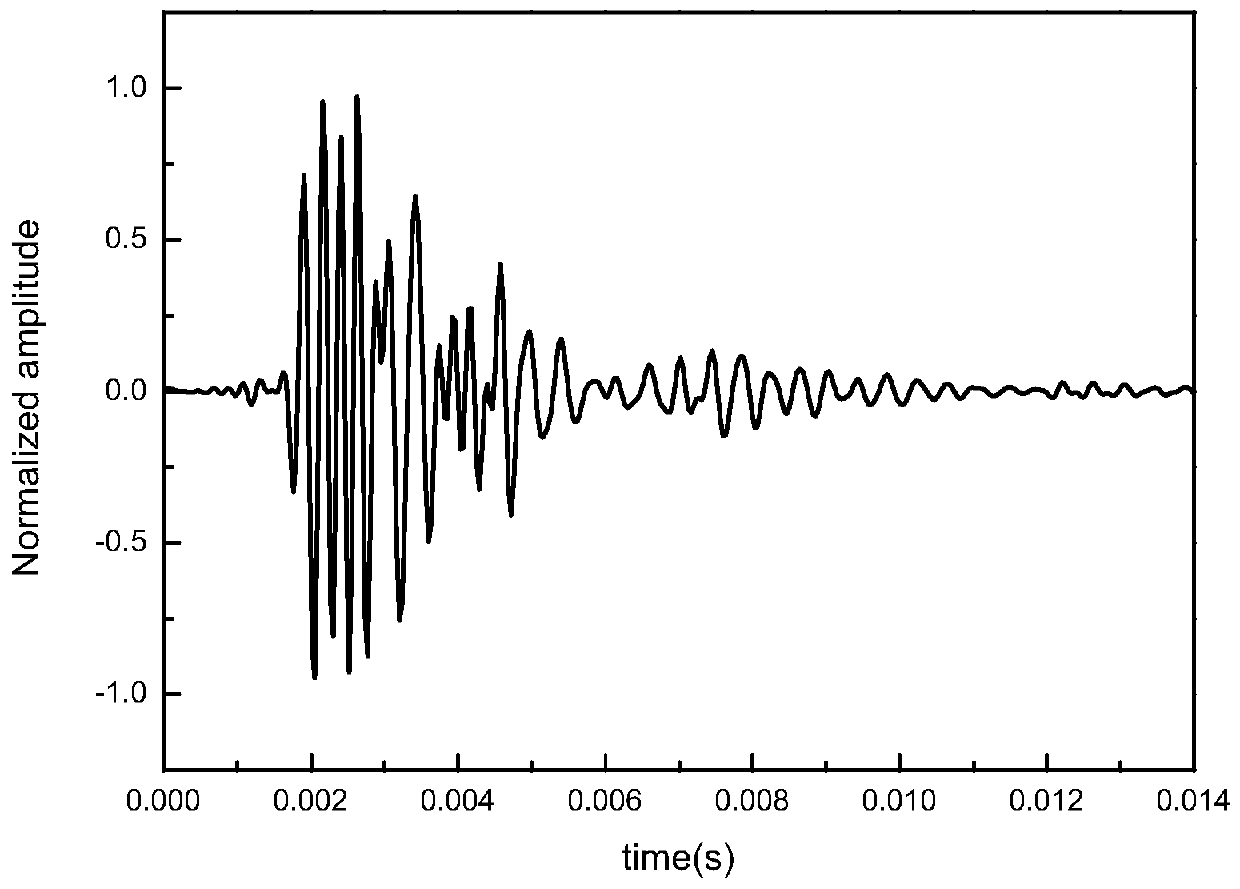
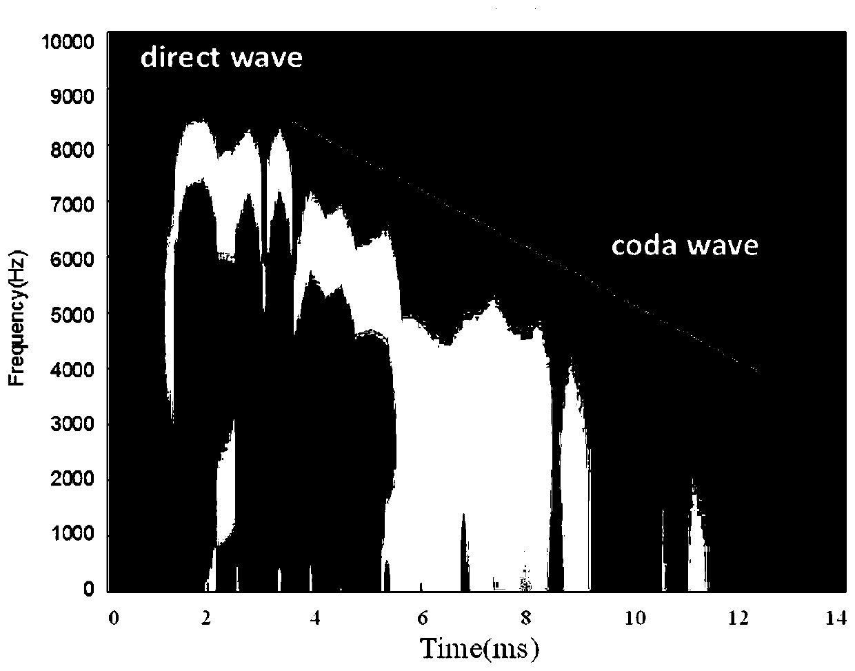
[0030] Step 2: Obtain the filtered dipole full wave train data v(t) at the processing depth position, set the window function g(t), and use the short-time Fourier transform (STFT), namely formula (1), to calculate the measured Power spectrum at different moments of the waveform:

[0031]

[0032] Among them, t is time, is angular frequency, f is frequency, and A(t, f) function gives the...


PUM


Abstract

The invention discloses a rock scattering attenuation calculation method using multi-parameter integrated inversion; the method comprises the following steps: carrying out array acoustic logging in a depth section, thus obtaining dipole array waveform data in the depth section; calculating a power spectrum of each depth point actual measuring waveform; building inversion objective functions; using the least squares to obtain the scattering attenuation of each depth point; loop executing step 2 to step 4, thus finally obtaining the scattering attenuation curve of the depth section. The method can accurately parse the acoustic logging data and extract scattering attenuation of elastic waves, thus providing valuable stratum information; compared with the large scale seismic wave scattering attenuation, the acoustic logging calculated scattering attenuation can provide the underground rock small scale heterogeneity information.

Description

technical field [0001] The invention relates to the fields of signal processing and pattern recognition, in particular to a feature extraction and classification recognition algorithm for mausoleum intrusion vibration signals suitable for a multi-grating sensor detection system. Background technique [0002] The scattering attenuation of the acoustic signal is an important parameter to describe the physical and chemical state of the earth medium, and it characterizes the variation trend of the wake amplitude with time. So far, the research on elastic wave scattering related to geophysical problems has mainly focused on the study of large-scale propagating seismic waves, but there are few reports on the study of borehole acoustic field. In conventional data processing of acoustic logging, scattered waves and wake waves are often regarded as noise and suppressed. Modern acoustic logging tools have been widely used in oil and gas exploration, and a large number of array acoust...

Claims


Application Information

Patent Timeline
Patent Type & Authority Patents(China)
IPC IPC(8): G01V1/40
CPCG01V1/40G01V2210/62
Inventor 黑创唐晓明庄春喜苏远大李振李修权
Owner YANGTZE UNIVERSITY
Why Eureka
Try Eureka