Welding device

A welding device and connecting shaft technology, applied in welding equipment, arc welding equipment, manufacturing tools, etc., can solve the problems of shortened service life, time-consuming and laborious, damaged power supply parts, etc., so as to improve the safety of plugging and reduce the manufacturing cost. , The effect of reducing equipment investment

Active Publication Date: 2017-06-13
泰安宝巨机械科技有限公司
View PDF6 Cites 9 Cited by
  • Summary
  • Abstract
  • Description
  • Claims
  • Application Information

AI Technical Summary

Problems solved by technology

[0002] At present, with the application of electric welding machines more and more widely, people have higher and higher safety requirements for the use of electric welding machines. However, electric welding machines rely on power supply connections to work, so whether the power supply connection is Safety is the prerequisite to ensure the normal use of electric welding machines. The existing electric welding machines are generally plugged and unplugged manually by personnel during the power supply connection process. However, due to the high voltage required by the electric welding machine, arcs are easily generated during the plugging process It is easy to cause electric shock to the user, which has a certain potential danger to the user, which will cause safety accidents and cause casualties, and the force of the personnel on the plug is unstable, which can easily lead to damage to the power supply part, shortening the service life and consuming time and effort. In addition, the existing electric welding machine does not have a prompt function during the plug-in power supply process, so that the operator cannot understand the power supply status of the electric welding machine at the first time, which has great disadvantages and brings inconvenience to the user.

Method used


Image

  • Welding device
  • Welding device
  • Welding device

Examples


Embodiment Construction

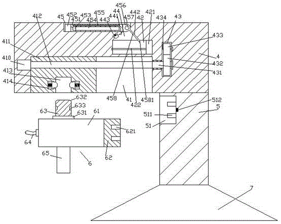
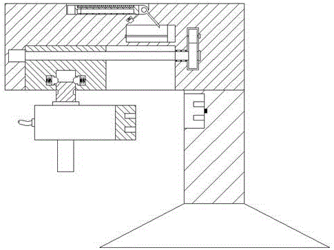
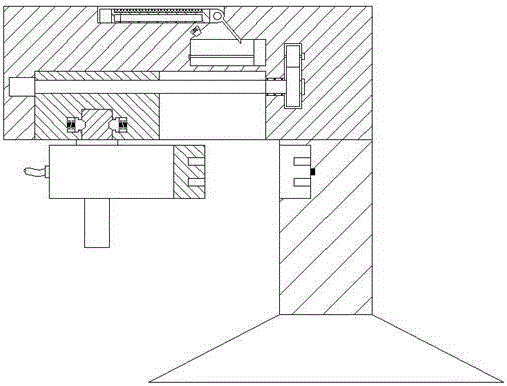
[0026] Such as Figure 1-Figure 6 As shown, a welding device of the present invention includes a base 7, a column 5 fixedly arranged above the base 7, a pushing part 4 fixedly connected to the top of the column 5 and extended to the left, and a plug part 6. An insertion slot 51 is provided in the left end surface of the column body 5, and an insert spring 511 arranged up and down symmetrically is arranged on the right inner wall of the insert slot 51, and the insert spring 511 between two sets of insert springs 511 Insert the sensor 512 on the inner wall on the right side of the groove 51, the top end surface of the pushing part 4 is provided with an installation groove 45, and the bottom end surface on the left side of the pushing part 4 is provided with a sliding groove 41, and the right side of the sliding groove 41 A sliding chamber 42 is provided in the pushing part 4 above, and a force transmission chamber 43 is provided in the pushing part 4 on the right side of the sli...


PUM


Abstract

The invention discloses a welding device. The welding device comprises a base, a cylinder, a push portion and a plug head portion, the cylinder is fixedly arranged above the base, the push portion is fixedly connected at the top of the cylinder and extends leftwards, a plugging groove is formed in the left end face of the cylinder, vertically symmetrical plugging springs are arranged on the inner right wall of the plugging groove, a sensor is arranged at the position, between the two plugging springs, of the inner right wall of the plugging groove, a mounting groove is formed in the top end face of the push portion, a sliding groove is formed in the left bottom end face of the push portion, a sliding cavity is formed in the push portion above the right side of the sliding groove, a force transfer cavity is formed in the position, on the right sides of the sliding cavity and the sliding groove, of the push portion, a first toothed wheel is arranged below the inner portion of the force transfer cavity, a second toothed wheel is connected to the top of the first toothed wheel in a mesh manner, a first rotating rod extending leftwards and rightwards is fixedly arranged on the first toothed wheel, and a second rotating rod extending leftwards and rightwards is fixedly arranged on the second toothed wheel. The welding device is simple in structure, convenient to operate, high in safety and capable of achieving plugging automatically and has a prompt function.

Description

technical field [0001] The invention relates to the field of welding technology, in particular to a welding device. Background technique [0002] At present, with the application of electric welding machines more and more widely, people have higher and higher safety requirements for the use of electric welding machines. However, electric welding machines rely on power supply connections to work, so whether the power supply connection is Safety is the prerequisite to ensure the normal use of electric welding machines. The existing electric welding machines are generally plugged and unplugged manually by personnel during the power supply connection process. However, due to the high voltage required by the electric welding machine, arcs are easily generated during the plugging process It is easy to cause electric shock to the user, which has a certain potential danger to the user, which will cause safety accidents and cause casualties, and the force of the personnel on the plug...

Claims


Application Information

Patent Timeline
Patent Type & Authority Applications(China)
IPC IPC(8): B23K9/10
CPCB23K9/1043
Inventor 蔡玉君
Owner 泰安宝巨机械科技有限公司
Why Eureka
Try Eureka