Spot welding device capable of adjusting welding head positions adaptively

A spot welding device and adaptable technology, applied in auxiliary devices, welding equipment, auxiliary welding equipment, etc., can solve the problems of inconvenient adjustment of position, limited application scope, complex structure, etc., and achieve the effect of facilitating spot welding operations.

Inactive Publication Date: 2017-06-13
CHONGQING YINCONG TECH CO LTD
7 Cites 0 Cited by

AI-Extracted Technical Summary

Problems solved by technology

[0002] The spot welding device in the prior art has a complex structure, and it is not ...

Method used

Rotate vertical adjustment handwheel 4, drive vertical screw mandrel 3 to rotate to drive longitudinal support plate 5 vertical adjustment positions back and forth; Rotate horizontal adjustment handwheel 9, drive horizontal screw mandrel 7 to rotate to drive horizontal support plate 8 vertical a...

Abstract

The invention discloses a spot welding device capable of adjusting welding head positions adaptively. The spot welding device comprises a base. A longitudinal adjusting mechanism, a transverse adjusting mechanism and a spot welding mechanism are arranged on the base. The longitudinal adjusting mechanism comprises a longitudinal lead screw, longitudinal guide rods, a longitudinal adjusting hand wheel and a longitudinal supporting plate, wherein the longitudinal guide rods are distributed on the two sides of the longitudinal lead screw; the axis of the longitudinal adjusting hand wheel is connected with one end of the longitudinal lead screw so that the longitudinal lead screw can be driven to rotate; the longitudinal guide rods are sleeved with the longitudinal supporting plate; and the longitudinal lead screw is in screw joint with the longitudinal supporting plate so as to drive the longitudinal supporting plate to slide. The transverse adjusting mechanism is similar to the longitudinal adjusting mechanism. By the adoption of the spot welding device, flexible switching of the spot welding positions can be achieved conveniently.

Application Domain

Welding/cutting auxillary devicesAuxillary welding devices +1

Technology Topic

Screw jointHead position +2

Image

  • Spot welding device capable of adjusting welding head positions adaptively
  • Spot welding device capable of adjusting welding head positions adaptively

Examples

  • Experimental program(1)

Example Embodiment

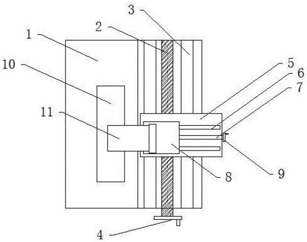
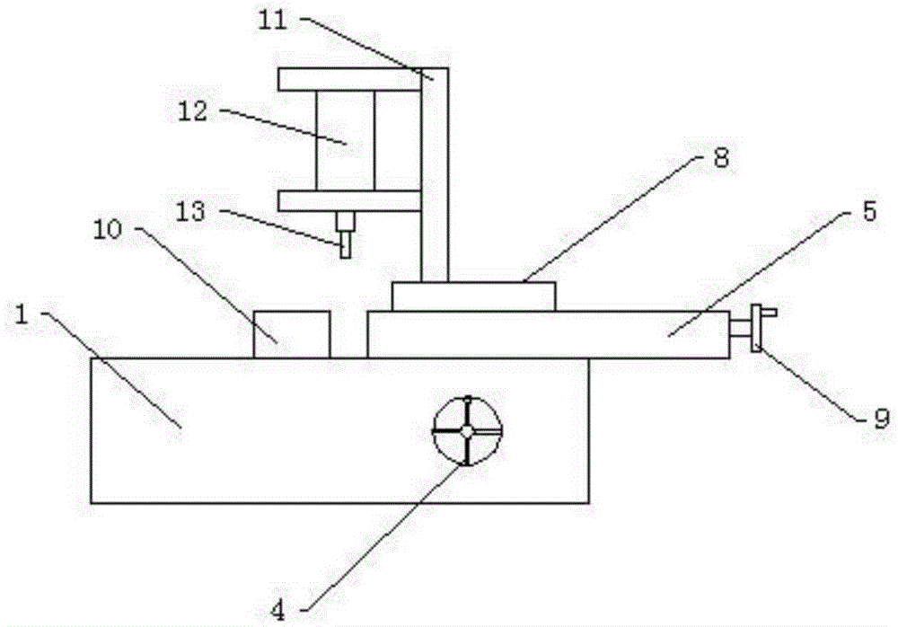
[0012] In order to have a further understanding and understanding of the structural features of the present invention and the achieved effects, the preferred embodiments and drawings are used in conjunction with detailed descriptions, and the description is as follows:
[0013] A spot welding device capable of adaptively adjusting the position of a welding head, comprising a base 1 provided with a longitudinal adjustment mechanism, a transverse adjustment mechanism, and a spot welding mechanism. The longitudinal adjustment mechanism includes a longitudinal screw 2, a longitudinal guide The rod 3, the longitudinal adjustment handwheel 4 and the longitudinal support plate 5, the top side of the base 1 is recessed inward to form a accommodating cavity, the screw rod 2 and the longitudinal guide rod 3 are longitudinally arranged in the accommodating cavity, and the longitudinal guide The rods 3 are distributed on both sides of the longitudinal screw rod 2. There are two longitudinal guide rods 3, which are equidistantly arranged on both sides of the longitudinal screw rod 2, and the axis of the longitudinal adjustment handwheel 4 is connected to one end of the longitudinal screw rod 2. , To drive the longitudinal screw 2 to rotate, the longitudinal support plate 5 is sleeved on the longitudinal guide rod 3, and the longitudinal screw 2 is screwed to the longitudinal support plate 5 to drive the longitudinal support plate 5 to slide.
[0014] The transverse adjustment mechanism includes a transverse guide rod 6, a transverse screw 7, a transverse adjustment hand wheel 9 and a transverse support plate 8. The transverse guide rod 6 and the transverse screw 7 are arranged on the top surface of the longitudinal support plate 5. The guide rods 6 are distributed on both sides of the transverse screw rod 7. There are two transverse guide rods 6 which are equidistantly arranged on both sides of the transverse screw rod 7. The axis of the horizontal adjustment handwheel 9 and one end of the transverse screw rod 7 It is connected to drive the horizontal screw 7 to rotate. The horizontal support plate 8 is sleeved on the horizontal guide rod 6. The horizontal screw 7 is screwed to the horizontal support plate 8 to drive the horizontal support plate 8 to slide.
[0015] The spot welding mechanism includes a workbench 10, a mounting seat 11, a spot welding cylinder 12, and a welding head 13. The mounting seat 11 is fixed on the top surface of the lateral support plate 8, and the spot welding cylinder 12 is fixed on the mounting seat 11. The welding head 13 is fixed to one end of the spot welding cylinder 12, and the welding head 13 vertically corresponds to the worktable 10 fixed on the base 1.
[0016] Turn the longitudinal adjustment hand wheel 4 to drive the longitudinal screw 3 to rotate to drive the longitudinal support plate 5 to adjust the position back and forth in the longitudinal direction; rotate the lateral adjustment hand wheel 9 to drive the horizontal screw 7 to rotate to drive the horizontal support plate 8 to adjust the position back and forth in the longitudinal direction. The spot welding machine is positioned to any position in the two-dimensional space, so that it is convenient to adjust the spot welding machine to any position on the operating table, and it is convenient for spot welding objects placed on the operating table.
[0017] The above shows and describes the basic principles, main features and advantages of the present invention. Those skilled in the industry should understand that the present invention is not limited by the above-mentioned embodiments. The above-mentioned embodiments and the specification describe only the principles of the present invention. The present invention may have various forms without departing from the spirit and scope of the present invention. Changes and improvements, these changes and improvements fall within the scope of the claimed invention. The scope of protection claimed by the present invention is defined by the appended claims and their equivalents.

PUM

no PUM

Description & Claims & Application Information

We can also present the details of the Description, Claims and Application information to help users get a comprehensive understanding of the technical details of the patent, such as background art, summary of invention, brief description of drawings, description of embodiments, and other original content. On the other hand, users can also determine the specific scope of protection of the technology through the list of claims; as well as understand the changes in the life cycle of the technology with the presentation of the patent timeline. Login to view more.
Why Eureka
Try Eureka