
High-safety power supply apparatus

A power supply device and safety technology, which is applied in the direction of coupling devices, components of connecting devices, circuits, etc., can solve problems such as potential safety hazards, poor circuit contact, and low safety, so as to prevent accidental electric shock accidents and improve plug-in efficiency , the effect of improving safety

Active Publication Date: 2017-06-20
STATE GRID SHANDONG ELECTRIC POWER
View PDF5 Cites 28 Cited by
  • Summary
  • Abstract
  • Description
  • Claims
  • Application Information

AI Technical Summary

Problems solved by technology

[0002] The power supply device is one of the indispensable accessories in the use of electrical equipment. It is mainly composed of two parts: the plug part and the socket part. The existing power supply device has poor stability during the plugging process, troublesome operation and low safety. High, the clamping force is not enough, and it is easy to be loosened by dragging and pulling, which will lead to poor contact of the circuit and affect the normal use of electrical equipment. It is very easy to induce electric shock accidents, and there is a great potential safety hazard

Method used


Image

  • High-safety power supply apparatus
  • High-safety power supply apparatus
  • High-safety power supply apparatus

Examples


Embodiment Construction

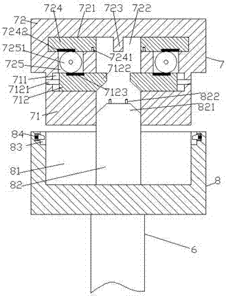
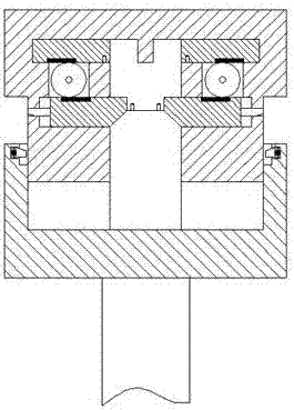
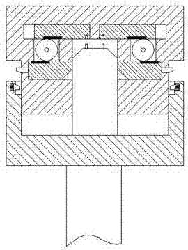
[0020] Such as Figure 1-Figure 5 As shown, a high-safety power supply device of the present invention includes a fixed socket 7 composed of a power supply part 72 and a joint part 71 and a plug 8 with a wire 6 at the bottom, and the wire 6 is connected to the electrical equipment. The inner center of the power supply part 72 is provided with a slot 722 extended downwards, the bottom of the slot 722 is set through the joint part 71, and the inner top wall of the slot 722 is provided with a baffle 723, the baffle The power supply part 72 on the left and right sides of the plate 723 is provided with a first chute 721, the bottom of the first chute 721 is provided with a cavity 725, and the joint part 71 at the bottom of the cavity 725 is provided with a The second chute 711, the first chute 721 is provided with a first sliding block 724, the inner side of the bottom of the first sliding block 724 is provided with a spring hole 7241, and the outer side of the spring hole 7241 Th...


PUM


Abstract

The invention discloses a high-safety power supply apparatus. The high-safety power supply apparatus comprises a fixed socket and a plug, wherein the fixed socket is formed by combining a power supply part with a combining part; the plug is provided with a wire at the bottom; an inserting slot, which is formed in a downward extension manner, is formed in the center of the interior of the power supply part; the bottom of the inserting slot is connected with the combining part in a run-through manner; a baffle is arranged on the top wall in the interior of the inserting slot; first sliding slots are formed in the power supply part on the left and right sides of the baffle respectively; an accommodating cavity is formed in the bottom of each first sliding slot; a second sliding slot is formed in the combining part at the bottom of each accommodating cavity; a first sliding connecting block is arranged in each first sliding slot; a spring inserting hole is formed in the inner side of the bottom of each first sliding connecting block; a first tooth-shaped part is arranged at the bottom of the first sliding connecting block outside the spring inserting hole; a tooth-shaped wheel connected with the bottom of the first tooth-shaped part in a meshing manner is arranged in each accommodating cavity; a second sliding connecting block is arranged in each second sliding slot; an inclined sliding locking rod, which is connected with the combining part in a run-through manner and is in sliding and connecting match, is arranged outside each second sliding connecting block; an inclined sliding bump part is arranged on one side, deviating from the inclined sliding locking rod, of each second sliding connecting block; and a second tooth-shaped part, which is connected with the bottom of the corresponding tooth-shaped wheel in a meshing manner, is arranged on the top end plane of each second sliding connecting block.

Description

technical field [0001] The invention relates to the technical field of electric power, in particular to a power supply device with high safety. Background technique [0002] The power supply device is one of the indispensable accessories in the use of electrical equipment. It is mainly composed of two parts: the plug part and the socket part. The existing power supply device has poor stability during the plugging process, troublesome operation and low safety. High, the clamping force is not enough, and it is easy to be loosened by dragging and pulling, which will lead to poor contact of the circuit and affect the normal use of electrical equipment. It is very easy to induce electric shock accidents under the situation of the environment, and there is a great potential safety hazard. Contents of the invention [0003] The technical problem to be solved by the present invention is to provide a power supply device with high safety, which can solve the above-mentioned problem...

Claims


Application Information

Patent Timeline
IPC IPC(8): H01R13/627H01R13/629H01R13/453
CPCH01R13/4534H01R13/6273H01R13/629
Inventor 卫杰
Owner STATE GRID SHANDONG ELECTRIC POWER
Learn More