
Circuit board special-shaped device plug-in device and path memory control method thereof

A plug-in device and circuit board technology, which is applied in the fields of printed circuit manufacturing, electrical components, electrical components, etc., can solve the problems of low work efficiency, inability to automate, and lack of versatility, so as to improve plug-in efficiency and improve operation reliability Effect

Pending Publication Date: 2021-01-01
SHUNDE POLYTECHNIC
View PDF0 Cites 0 Cited by
  • Summary
  • Abstract
  • Description
  • Claims
  • Application Information

AI Technical Summary

Problems solved by technology

With the development of technology, PCB board insertion has gradually changed from manual insertion to automatic equipment insertion to improve insertion efficiency. Insertion is not universal. When it is necessary to insert special-shaped devices such as relays on the PCB, since the special-shaped devices are packed in bulk, they cannot be automatically and continuously loaded. Manual plug-in operations are still required, which cannot be automated and continuous. Optimized insertion operation, low work efficiency

Method used


Image

  • Circuit board special-shaped device plug-in device and path memory control method thereof
  • Circuit board special-shaped device plug-in device and path memory control method thereof
  • Circuit board special-shaped device plug-in device and path memory control method thereof

Examples


Embodiment 1

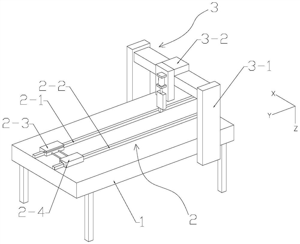
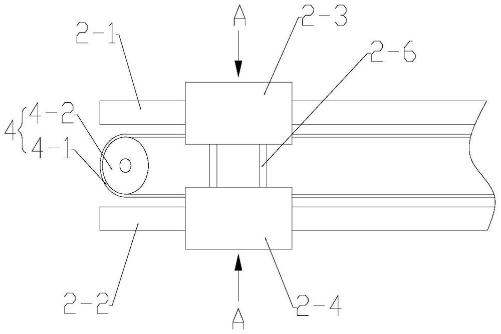
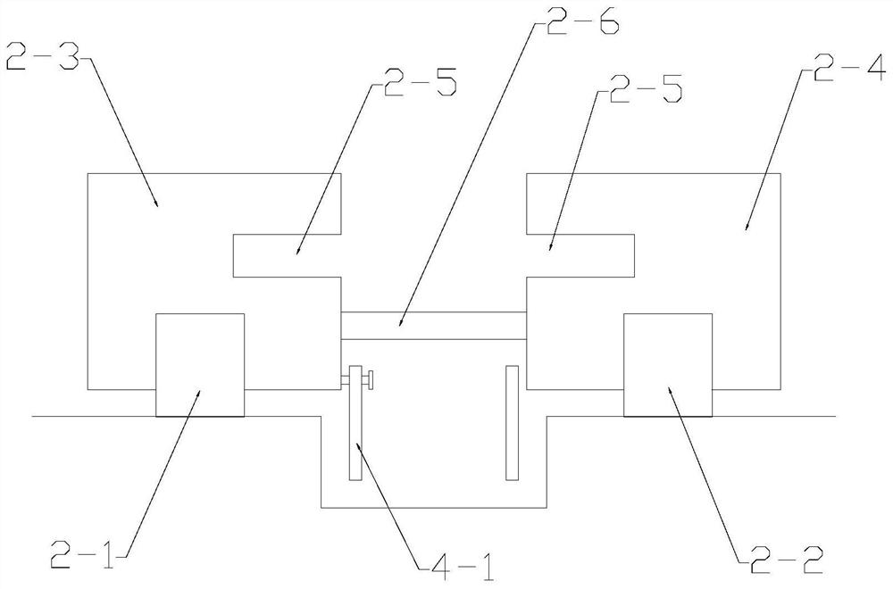
[0027] Such as figure 1 As shown, the present invention is a circuit board special-shaped device plug-in device, including a frame 1, a circuit board conveying mechanism 2 and a terminal insertion mechanism 3 arranged on the frame 1, characterized in that the circuit board conveying The mechanism 2 includes a first guide rail 2-1, a second guide rail 2-2 arranged in parallel along the Y-axis direction, a first slider 2-3 movably connected to the first guide rail 2-1, and a first slider 2-3 movably connected to the first guide rail 2-1. The second slider 2-4 on the second guide rail 2-2, wherein the first slider 2-3 and the second slider 2-4 are driven by the power device 4 along the first guide rail 2 -1 slides with the second guide rail 2-2, and the inner middle part of the first slider 2-3 and the second slider 2-4 is provided with an accommodating cavity 2-5 for accommodating a circuit board;

[0028] The terminal insertion mechanism 3 includes a gantry 3-1 and an insertio...

Embodiment 2

[0039] The structure of a plug-in device for special-shaped circuit boards provided in this embodiment is basically the same as in Embodiment 1, the difference is that: Figure 6 As shown, the number of its terminal insertion mechanism is 3, which can respectively carry out different path memory for the insertion head assembly on it, and can realize the continuous insertion of different types of special-shaped devices on the same production line, greatly improving the insertion efficiency. In other embodiments, multiple terminal insertion mechanisms may also be provided according to production requirements, which is not limited to this embodiment.


PUM


Abstract

The invention discloses a circuit board special-shaped device plug-in device, which comprises a rack, and a circuit board conveying mechanism and a terminal plug-in mounting mechanism which are arranged on the rack, and is characterized in that the circuit board conveying mechanism comprises a first guide rail, a second guide rail, a first sliding block and a second sliding block which are arranged in parallel along the Y-axis direction; the first sliding block and the second sliding block are driven by a power device to slide along the first guide rail and the second guide rail respectively.A containing cavity for containing a circuit board is formed in the middle of the inner side of the first sliding block and the middle of the inner side of the second sliding block. The terminal plug-in mounting mechanism comprises a portal frame and a plug-in mounting head assembly movably connected to the portal frame. According to the invention, plug-in mounting operation can be automatically and continuously performed on the circuit board special-shaped device, and the production efficiency is greatly improved.

Description

technical field [0001] The invention relates to the technical field of mechanical equipment, in particular to a plug-in device for special-shaped components on a circuit board and a path memory control method thereof. Background technique [0002] Printed circuit board (PCB) assembly is generally divided into two types: automatic assembly and manual assembly according to the type of components. Components mounted on the board through holes are inserted manually. With the development of technology, PCB board insertion has gradually changed from manual insertion to automatic equipment insertion to improve insertion efficiency. Insertion is not universal. When it is necessary to insert special-shaped devices such as relays on the PCB, since the special-shaped devices are packed in bulk, they cannot be automatically and continuously loaded. Manual plug-in operations are still required, which cannot be automated and continuous. Optimized insertion operation, low work efficiency...

Claims


Application Information

Patent Timeline
IPC IPC(8): H05K3/30H05K13/00H05K13/04H05K13/08
CPCH05K3/306H05K13/0061H05K13/046H05K13/0406H05K13/0812
Inventor 刘丰华陈新肖文平张立荣郭国兴
Owner SHUNDE POLYTECHNIC
Learn More