
Testing device for dynamic rigidity of engine suspension

An engine mount and testing device technology, which is applied in the testing of machine/structural components, measuring devices, and elasticity testing, etc., can solve the problems of low testing accuracy of engine mount dynamic stiffness, and achieve the effect of accurate dynamic stiffness value.

Inactive Publication Date: 2017-06-30
BEIJING INSTITUTE OF TECHNOLOGYGY
View PDF3 Cites 3 Cited by
  • Summary
  • Abstract
  • Description
  • Claims
  • Application Information

AI Technical Summary

Problems solved by technology

[0005] The purpose of the present invention is to solve the problem of low test accuracy of engine mount dynamic stiffness and provide a test device for engine mount dynamic stiffness

Method used


Image

  • Testing device for dynamic rigidity of engine suspension
  • Testing device for dynamic rigidity of engine suspension
  • Testing device for dynamic rigidity of engine suspension

Examples


Embodiment 1

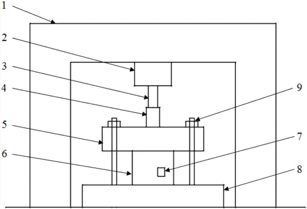
[0027] Utilize the present invention to test the dynamic stiffness of the engine rubber mount provided by a military diesel engine research institute, including a control system 1, a vibrator 2, an exciting rod 3, a force hammer 4, a preloaded mass 5, a mount to be tested 6, Sensor 7, base 8 and bolt 9; as figure 1 shown.

[0028] Connection relationship:

[0029] The control system 1 includes a 32-channel LMS data acquisition system and a power amplifier; one end of the power amplifier is connected to the 32-channel LMS data acquisition system, and the other end is connected to the exciter 2;

[0030] The suspension to be tested 6 and the preloaded mass 5 are placed in sequence above the base 8, and then the suspension to be tested 6 and the preloaded mass 5 are fixedly installed on the base 8 through the bolt 9; the suspension to be tested can be adjusted by adjusting the bolt 9 Set 6 to apply different preloads; the top of the preloaded mass 5 is fixedly connected to the ...


PUM


Abstract

The invention relates to a testing device for dynamic rigidity of an engine suspension, wherein the testing device belongs to the field of vehicle vibration testing. The testing device comprises the components of a control system, an exciting system, a force sensor, an acceleration sensor, a to-be-tested suspension, a pre-loading mass block, a base and bolts, wherein the control system is composed of a 32-channel LMS data acquisition system and a power amplifier, and the exciting system is composed of a vibration exciter, an exciting rod and a hammer. The control system makes the vibration exciter generate an exciting force for generating an engine dynamic load. The sensor acquires a response and transmits the response to an LMS data acquisition system. In the LMS data acquisition system, data processing is performed for obtaining the dynamic rigidity of the to-be-tested suspension. Compared with prior art, the testing device is advantageous in that vibration exciter loading is utilized; force bearing condition of the engine suspension in an actual working state can be more accurately simulated; a more accurate dynamic rigidity can be obtained; and the testing device has relatively high popularization value.

Description

technical field [0001] The invention relates to a testing device for the dynamic stiffness of an engine mount, which belongs to the field of vehicle vibration testing. Background technique [0002] In recent years, more and more attention has been paid to the NVH performance of automobiles. The engine mount system elastically connects the powertrain to the frame, and can isolate the vibration between the powertrain and the frame in two directions. Therefore, the design of the engine mount system directly affects the transmission of engine vibration to the frame and affects the NVH performance of the vehicle. [0003] When the engine is working normally, the force acting on the mount is the dynamic load. Therefore, the exploration of the ability to resist deformation under the dynamic load of the mount, that is, the dynamic stiffness, has strong practical significance for the improvement of the mount system. [0004] In the prior art, the suspension is mainly manually tapped...

Claims


Application Information

Patent Timeline
Patent Type & Authority Applications(China)
IPC IPC(8): G01M5/00G01M17/04
CPCG01M5/0066G01M5/0075G01M17/04
Inventor 王纪福冯慧华朱乘军匡宇宵牟小龙田静宜杨征葳
Owner BEIJING INSTITUTE OF TECHNOLOGYGY
Learn More