Orthogonal decomposition based shear deformation testing method adopting laser displacement meters

A laser displacement meter and shear deformation technology, which is applied in the direction of using a stable shear force to test the strength of materials, measuring devices, analyzing materials, etc., which can solve the problems of unavailability and large data errors.

Inactive Publication Date: 2017-06-30
SOUTHWEST JIAOTONG UNIV
View PDF3 Cites 5 Cited by
  • Summary
  • Abstract
  • Description
  • Claims
  • Application Information

AI Technical Summary

Problems solved by technology

The data obtained by the test has large errors or is not available

Method used


Image

  • Orthogonal decomposition based shear deformation testing method adopting laser displacement meters
  • Orthogonal decomposition based shear deformation testing method adopting laser displacement meters
  • Orthogonal decomposition based shear deformation testing method adopting laser displacement meters

Examples


Embodiment Construction

[0015] The present invention will be further described in detail below in conjunction with the accompanying drawings and specific embodiments.

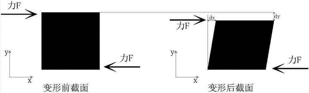
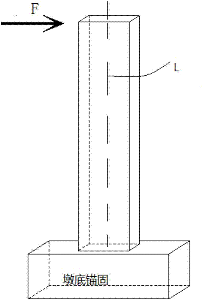
[0016] figure 1 When the specimen is subjected to shear force, the shear deformation of the cross-section mainly has displacements in two directions (Dx, Dy). In the solid section of the specimen, the macro-accumulated shear deformation can also be decomposed into two In the orthogonal direction, the deformation in two directions is tested separately. image 3 It is a schematic diagram of the placement of the specimen, and L in the figure is the neutral axis of the specimen.

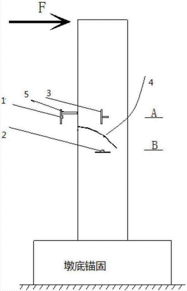
[0017] image 3 is the arrangement scheme of the laser displacement meter, and the laser displacement meter is reasonably arranged at the section where the oblique cracks occur in the specimen. The distance between the two directions is similar, the laser displacement gauge in the height direction (y direction) is arranged at the position of the neutral axis,...


PUM


Abstract

The invention discloses an orthogonal decomposition based shear deformation testing method adopting laser displacement meters. One side surface of a zone, to be subjected to shear deformation, of a test piece is selected, an x-direction laser displacement meter 1 and a y-direction laser displacement meter 2 are arranged in the width direction and the height direction of the test piece respectively, a laser displacement meter transmitting plate 3 is also fixed on the side surface of the test piece, parallel to a neutral axis L and located at an orthogonal surveying and mapping point of the x-direction laser displacement meter 1 and the y-direction laser displacement meter 2; after tangential load is applied, and x-direction displacement variation Sx and y-direction displacement variation Sy in the zone are tested respectively on the basis of the laser displacement meters, so that the average shear strain in the zone is obtained. With adoption of the method, measurement precision of shear deformation of the test piece can be improved effectively, and data has high utilization ratio.

Description

technical field [0001] The invention relates to a test method for testing shear deformation of a specimen, in particular to a new method for testing shear deformation based on an orthogonal decomposition laser displacement meter. Background technique [0002] The traditional methods of testing shear deformation mostly use tensile displacement sensors or dial gauges, which are inconvenient in layout, low in precision, low in linearity, and poor in sensitivity. The inaccuracy of the layout direction (single direction) leads to the measured shear The shear deformation error is large, and sometimes the shear deformation cannot be measured, so that the cognition of the actual deformation of the specimen is greatly limited. After analysis, it was found that the main reason was the defect in the test method and test equipment. The data obtained by the test has large errors or is unavailable. Contents of the invention [0003] In view of the above deficiencies in the prior art, ...

Claims


Application Information

Patent Timeline
IPC IPC(8): G01N3/24G01N3/06
CPCG01N3/24G01N3/068G01N2203/0025G01N2203/0258G01N2203/0641G01N2203/0682
Inventor 邵长江孙南昌佐雪韦旺漆启明胡晨旭
Owner SOUTHWEST JIAOTONG UNIV
Why Eureka
Try Eureka