Ink coating equipment and an ink coating method

A coating device and coating technology, which is applied to the surface coating liquid device, coating, printing, etc., can solve the problems of mixing into other blocks, defective blocks, mixed color and light emission, etc., and achieve the goal of maintaining manufacturing efficiency Effect

Active Publication Date: 2017-07-04
PANASONIC INTELLECTUAL PROPERTY MANAGEMENT CO LTD
View PDF12 Cites 4 Cited by
  • Summary
  • Abstract
  • Description
  • Claims
  • Application Information

AI Technical Summary

Problems solved by technology

In this way, in the case of non-discharging nozzles in the blocks 53b and 53c, if two drops are to be ejected, it may be applied outside the block, or the specified amount of liquid droplets may not be sprayed in the block, or mixed with To other blocks, etc., there are problems that cause defective blocks and mixed colors to emit light

Method used


Image

  • Ink coating equipment and an ink coating method
  • Ink coating equipment and an ink coating method
  • Ink coating equipment and an ink coating method

Examples


Embodiment approach 1

[0129] Next, Embodiment 1 of the present invention will be described.

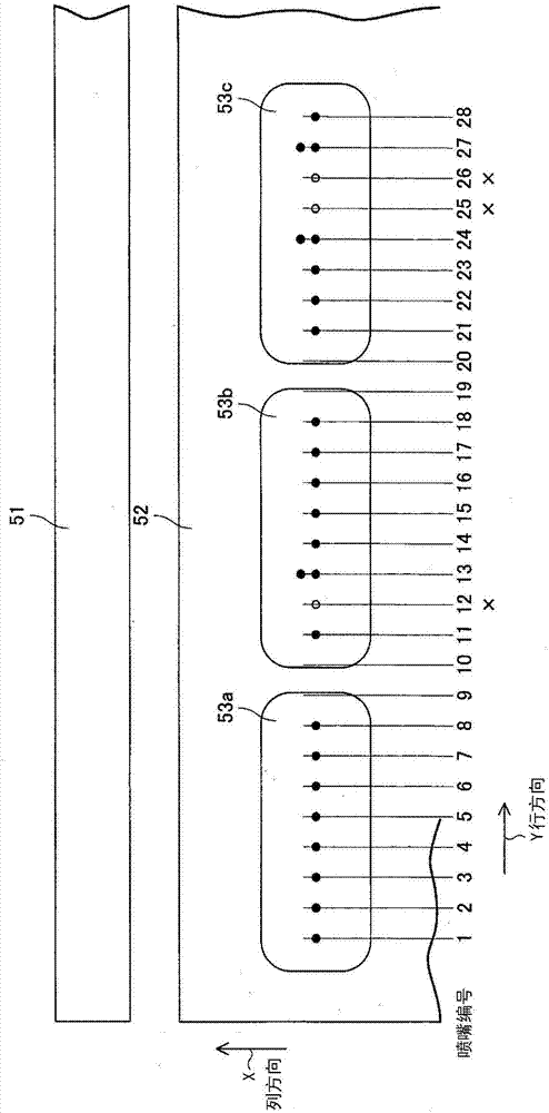
[0130] Figure 6 It is a conceptual diagram of the ink application device in Embodiment 1. Figure 7 In the case of printing with this ink application device, the application image 3 that two-dimensionally marks the ink ejection position and non-ejection nozzle information of the used nozzles are shown.

[0131] In this example, there are nine blocks 1c, and each block 1c is filled with a necessary amount of ink for three drops of ejection. The black circle is the spraying position, and the white circle is the non-spraying position.

[0132] Figure 7 The coating image 3 of is constituted by a two-dimensional coordinate system of the arrangement direction of the nozzles (row direction Y) and the scanning direction of the nozzles (column direction X). In the coating image 3, the dots at which ink should be ejected from the nozzles are connected by dotted lines to form a grid. The intersection point bec...

Embodiment approach 2

[0227] In Embodiment 2, the case of spraying to different types of panels will be described. Items not described are the same as those in Embodiment 1.

[0228] Figure 15 (a) is a plan view of a substrate 40 in which two types of display panels coexist, which is the object of the second embodiment. On the substrate 40, three small display panels 41a to 41c are arranged on the left side, and a large display panel 42 is arranged on the right side. 2k panels of 300 ppi are arranged on the small display panels 41a to 41c. A 4k panel of 200ppi is arranged on the large display panel 42 . As a result, blocks 1c of 300ppi and 200ppi are placed in the respective panel areas.

[0229] Figure 15(b) shows the positional relationship of ink ejection in the up-down direction (scanning direction, X direction) between the first block 1c of the small display panels 41a to 41c and the block 1c of the large display panel 42 .

[0230] In the block 1c of the small display panel 41a, ink i...

Embodiment approach 1、2

[0258] Embodiments 1 and 2 can be combined together.


PUM


Abstract

The present invention provides an ink coating equipment and an ink coating method which can drop assigned number of dropping without exceeding a block in the condition that the size of the column direction X of the block is shortened. The device comprises a shower nozzle configured to spray ink liquid from nozzles; a stand keeping a coating object; a spraying timing keeping portion configured to output a reference spraying timing; a non-spraying nozzle data portion configured to store the position of non-spraying nozzle; a nozzle direction spraying quantity information portion configured to keep the nozzle direction and the spraying quantity information based on a coating image; and a control portion obtained by driving the nozzle in the condition that the nozzles of the ink liquid are not enough at the block so as to spray ink liquid for many times to other nozzles on time from the nozzles of the block.

Description

technical field [0001] The present invention relates to an ink application device and an ink application method. In particular, it relates to a light-emitting layer of a display panel for a display device such as organic EL (ElectroLuminescence), and an ink application device equipped with an inkjet head and an ink application method used in other application processes. Background technique [0002] As a method of forming the organic light-emitting layer of an organic EL display panel, there is a method of applying a low-molecular organic material or a high-molecular organic material together with a solvent. One of the typical methods of forming an organic light-emitting layer by applying a solvent includes a method of discharging ink droplets containing an organic light-emitting material onto a segment of a display substrate using an ink application device. At this time, the ejected ink droplets contain the organic light-emitting material and the solvent. [0003] A gener...

Claims


Application Information

Patent Timeline
IPC IPC(8): B41J2/135
CPCB41J2/135B05C5/0225B05C11/1002B05D1/26H01L21/02282H10K71/135H10K71/00
Inventor 南云孝夫
Owner PANASONIC INTELLECTUAL PROPERTY MANAGEMENT CO LTD
Why Eureka
Try Eureka