
Applicator

A coating and device technology, applied to hair or scalp washing devices, packaging, travel or camping equipment, etc., can solve the problems of hindering sufficient supply of coating liquid and hindering operability, etc., to achieve easy fixation and ensure flow path Effect

Active Publication Date: 2020-06-30
MITSUBISHI PENCIL CO LTD
View PDF7 Cites 0 Cited by
  • Summary
  • Abstract
  • Description
  • Claims
  • Application Information

AI Technical Summary

Problems solved by technology

In order to eliminate deviation, the operator cannot cope with manual assembly (assembly by hand), so special equipment is required, which hinders operability
[0006] Additionally, if Figure 10 As shown in (b), in the vicinity of the pin hole, when the pin a is driven in, the coating core b bulges, and the part b1 of the coating core b sandwiched by the pin a and the inner wall of the guide shaft c restricts the flow of the coating core b path, therefore, there is a problem of hindering the sufficient supply of the coating liquid

Method used


Image

  • Applicator
  • Applicator
  • Applicator

Examples


Embodiment Construction

[0036] Hereinafter, embodiments of the present invention will be described with reference to the drawings.

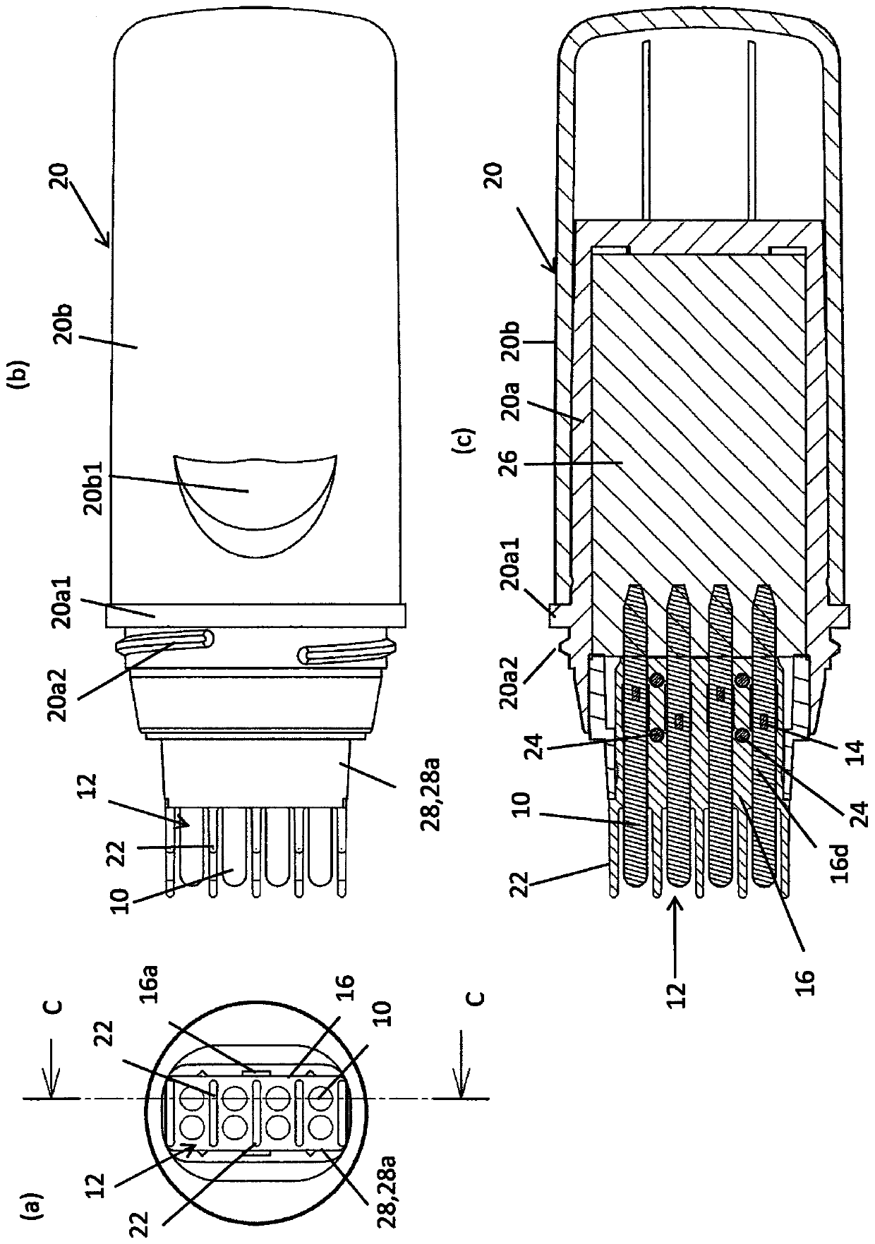
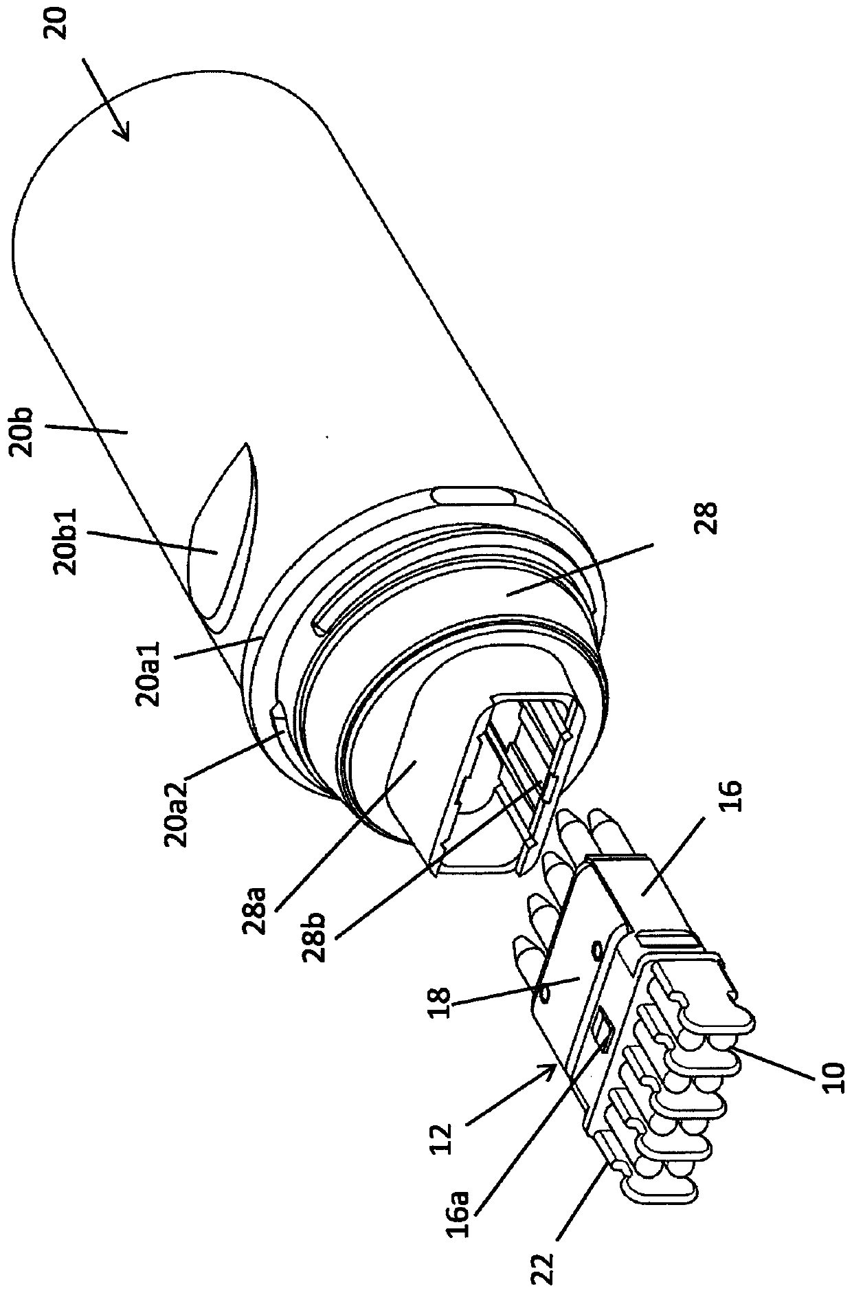
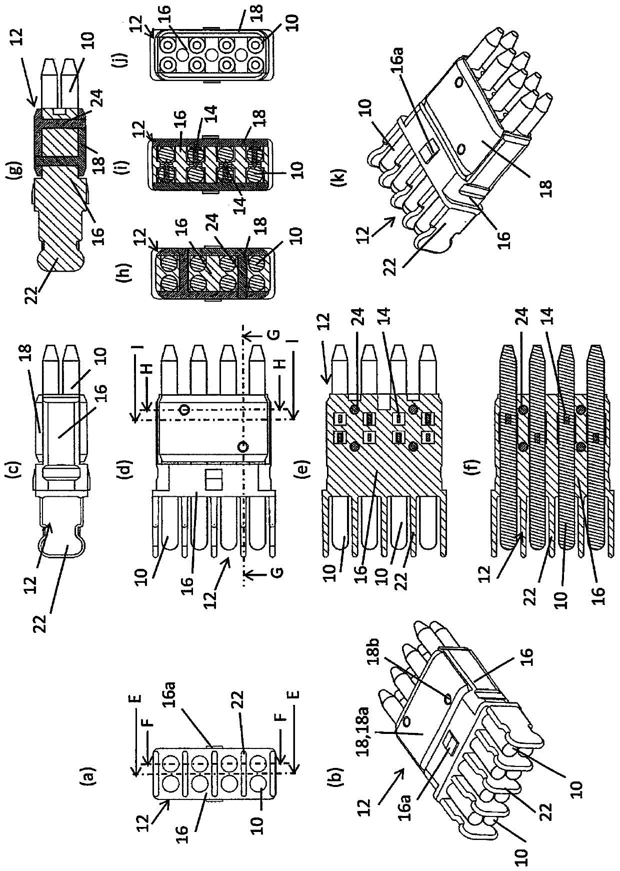
[0037] figure 1 , figure 2 It is explanatory drawing of the applicator of embodiment of this invention, image 3 , Figure 4 It is an explanatory figure of the application part, Figure 5 It is an explanatory diagram of the core base, Figure 6 It is an explanatory figure of the core fixing tool, Figure 7 is the guide shaft, Figure 8 , Figure 9 It is an action explanatory diagram.

[0038] The applicator of the embodiment is provided with an applicator 12 having a plurality of applicators 10 .

[0039] The applicator 12 includes a core base 16 on which an applicator is mounted, a flat main body, and a fixing member 18 from which a plurality of protrusions 14 and guide pins 24 protrude. In the state where the protrusion 14 of the fixing member 18 is pierced into the applicator 10, the guide pin 24 is installed to fix the fixing member 18 to the core base 16...


PUM

PropertyMeasurementUnit
lengthaaaaaaaaaa

Abstract

The present invention provides an applicator capable of fixing an applicator easily and securing a flow path of a coating liquid. An applicator provided with an applicator having an applicator, the applicator having a core base on which the applicator is mounted and a fixing member protruding from a main body with a plurality of protrusions, when the protrusions of the fixing member are pierced into In the state of the applied body, the fixing member is fixed to the core base to fix the applied body to the core base, and in the fixed state of the applied body, the applied part is attached to the guide shaft .

Description

technical field [0001] The present invention relates to an applicator to which an applicator, such as a applicator core, is fixed, and the applicator core is obtained by bundling a porous core capable of guiding a applicator liquid by capillary action, and fibers. Background technique [0002] In the applicator, as the fixing means of the coating core, conventionally, the coating core is provided with a concave portion, a guide shaft is provided with a convex portion to fit the convex portion and the concave portion, or the coating core is fastened and fixed, etc. . [0003] The former means of providing a concave portion on the coating wick reduces the cross-sectional area of ​​the coating wick, and the latter means of fastening the coating wick results in closure of the flow path due to fastening. Both methods have a problem that smooth liquid delivery is difficult. [0004] Therefore, in the applicator described in Patent Document 1, a pin is driven into a resin-made gu...

Claims


Application Information

Patent Timeline
Patent Type & Authority Patents(China)
IPC IPC(8): B65D47/44
CPCB65D47/44A45D24/24A45D19/026A45D19/0066
Inventor 齐籐祥一
Owner MITSUBISHI PENCIL CO LTD
Learn More