Expansion radiator for a hermetically closed electrical transformer

a technology of expansion radiator and electrical transformer, which is applied in the direction of transformer/inductance cooling, indirect heat exchanger, light and heating apparatus, etc., can solve the problems of accelerating the aging process, reducing the service life of insulating paper, and expansion radiator cannot of course be constructed to compensate for expansion volumes of any size, so as to achieve the effect of cheap manufacturing and better cooling

Active Publication Date: 2015-11-12
SIEMENS ENERGY GLOBAL GMBH & CO KG
View PDF1 Cites 3 Cited by
  • Summary
  • Abstract
  • Description
  • Claims
  • Application Information

AI Technical Summary

Benefits of technology

The invention is an expansion radiator for a hermetically sealed electrical transformer or choke. It is designed to improve cooling while being inexpensive to manufacture. The radiator has expansion corrugations with flow guiding parts that direct the cooling fluid towards the outer edge of the radiator, resulting in better cooling and lower oil temperature. This reduces the need for additional oil in the transformer tank and increases the service life of the radiator. The flow guiding part can be easily integrated into the manufacture of the collector, keeping the overall costs low. The radiator can also be designed to have a decreasing cross-section of the flow guiding part, allowing the cooling medium to be efficiently directed in the direction of the nose and subsequently flow in the direction of a side of the expansion corrugation.

Problems solved by technology

In this equalizing vessel, contact with the ambient air causes an increase in moisture and oxygen in the insulating oil in spite of dehumidifiers, thereby accelerating the aging process and reducing the service life of the insulating paper.
However, an expansion radiator cannot of course be constructed to compensate an expansion volume of any size, but only a maximum expansion volume associated with its structural shape.
In both embodiments the two sheet metal sections of the radiator elements are welded circumferentially to one another, making them costly to manufacture.
As a result, however, the upper part of the corrugated sheet only contributes to the cooling effect to a reduced extent.

Method used


Image

  • Expansion radiator for a hermetically closed  electrical transformer
  • Expansion radiator for a hermetically closed  electrical transformer
  • Expansion radiator for a hermetically closed  electrical transformer

Examples


Embodiment Construction

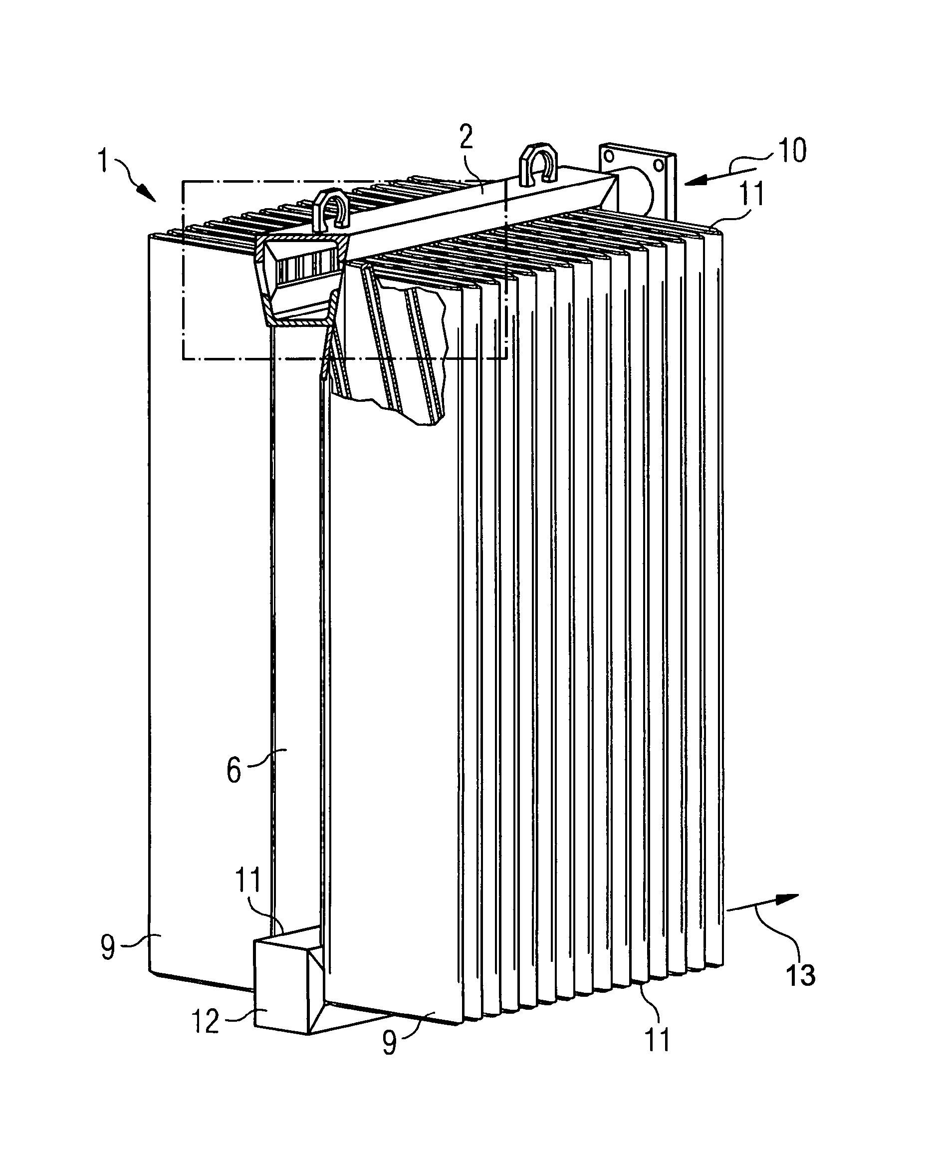
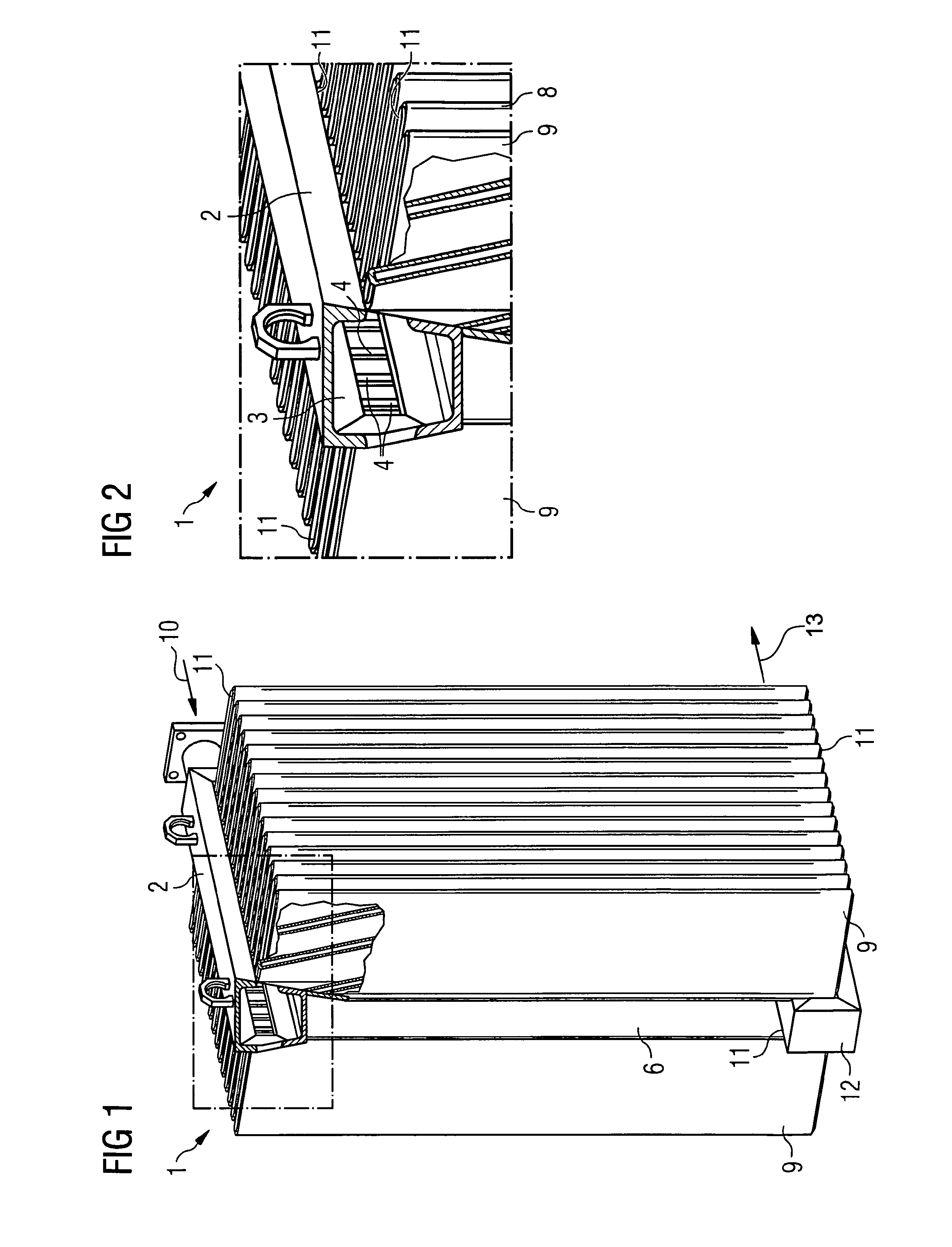
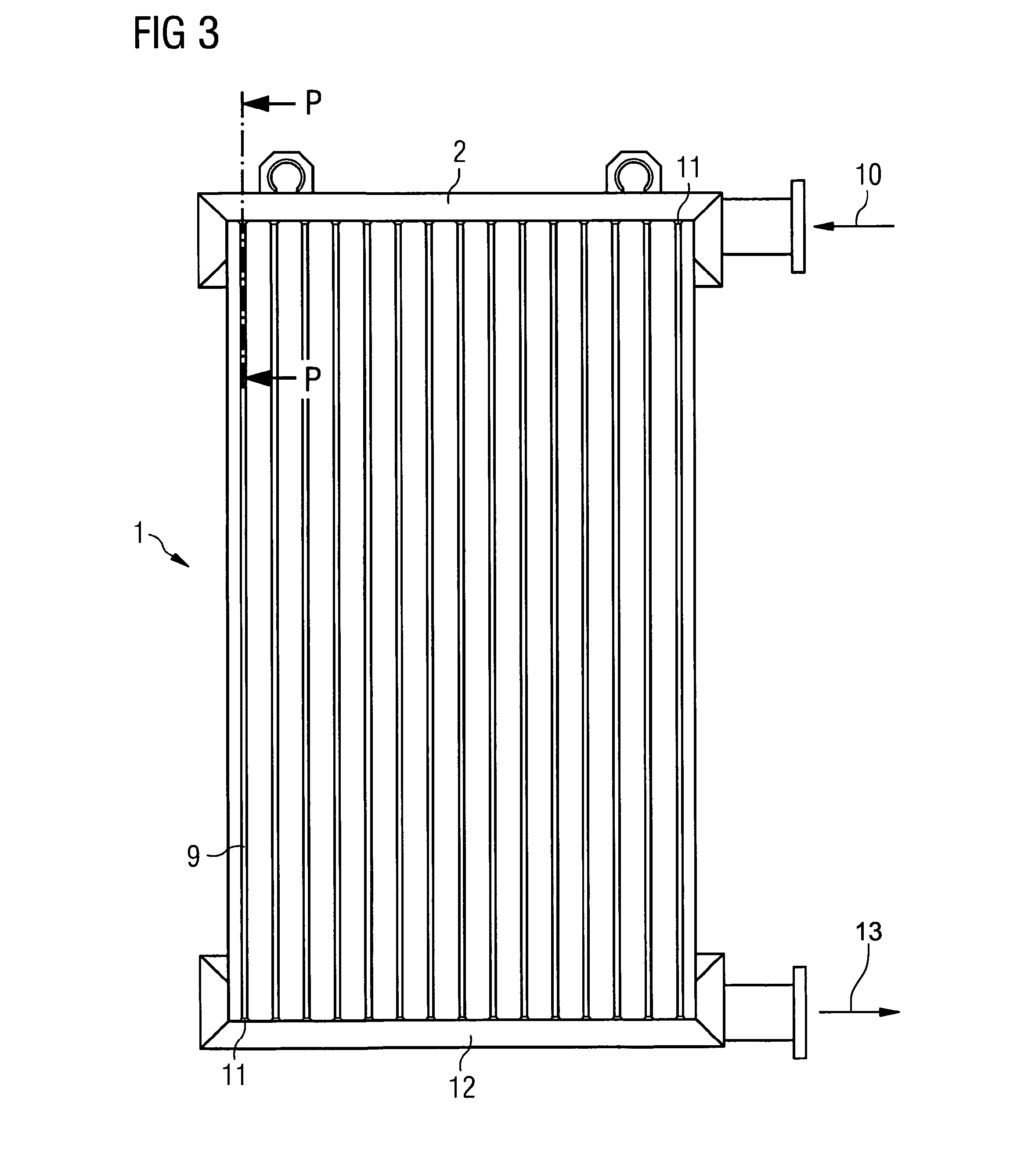
[0022]FIG. 1 shows a perspective view of an expansion radiator 1 according to the invention. The expansion radiator 1 basically consists of two rows of expansion corrugations 9, each disposed on either side of an upper collector 2 and a lower collector 12. The backs of the expansion corrugations 9 are welded to a cover sheet 6 by means of a welded joint 11 in the inside area between the two collectors 2,12. The sides of the expansion corrugation are likewise welded top and bottom in a liquid-tight manner. The cross-section of the collector 2 is rectangular in the example shown and leads into a circular pipe having a flange for connection to a transformer or a choke. During operation, the heat exchange medium (insulating oil, e.g. transformer oil) flows into this flange in the direction of the arrow 10 and leaves the expansion radiator 1 at its lower collector 12. The structural design is symmetrical with respect to an imaginary central plane running through the collectors 2, 12. Bot...


PUM


Abstract

An expansion radiator for a hermetically closed electrical transformer or a throttle. A heat exchange fluid is delivered to the radiator via an inflow, passed through an expansion shaft cavity formed by an expansion shaft and an associated cover part, and then drained off via an outflow. A flow guiding part which steers a flow direction of the heat exchange fluid is arranged in a mouth region between the inflow and the expansion shaft cavity.

Description

TECHNICAL FIELD[0001]The invention relates to an expansion radiator for a hermetically sealed electrical transformer or a choke, to which expansion radiator a heat exchange fluid is supplied via an inflow means, passed through an expansion corrugation cavity formed by an expansion corrugation and an associated cover part, and then drained via outflow means.PRIOR ART[0002]Electrical transformers or chokes of the type used in power distribution systems are usually cooled using an insulating oil. In order to compensate the oil volume fluctuations occurring during operation, an equalizing vessel is provided in the top of the transformer tank. In this equalizing vessel, contact with the ambient air causes an increase in moisture and oxygen in the insulating oil in spite of dehumidifiers, thereby accelerating the aging process and reducing the service life of the insulating paper. In order to counteract this accelerated aging process of the insulating paper it is also known to seal off th...

Claims


Application Information

Patent Timeline
IPC IPC(8): H01F27/14H01F27/02
CPCH01F27/022H01F27/14F28F13/06F28D1/0316F28D1/0358F28D2021/0031F28D2021/0049
Inventor PEINBAUER, RICHARDWENIGER, MARTIN
Owner SIEMENS ENERGY GLOBAL GMBH & CO KG
Why Eureka
Try Eureka