Signal transmission device

A signal transmission and signal technology, applied in the field of information, can solve the problems of loose card connection, interruption of signal transmission, user inconvenience, etc., and achieve the effect of preventing card connection loosening and improving stability.

Inactive Publication Date: 2017-07-21
荆门市合方越达电子科技有限公司
View PDF7 Cites 3 Cited by
  • Summary
  • Abstract
  • Description
  • Claims
  • Application Information

AI Technical Summary

Problems solved by technology

[0002] With the rapid development of the information age, the use of computers is becoming more and more widespread. However, computers need to be connected to the network through a network cable before they can be used. The existing connection to the network is generally through the signal connection terminal (crystal plug). ) is clamped in the signal output hole to realize the connection work. Although the existing operation method of realizing the signal transmission work by clamping is simple, its clamping effect is not reliable, and it is very easy to be dragged and pulled by the network cable It will affect the loosening of the clamping connection, interrupt the signal transmission, and bring great inconvenience to the user. At the same time, the existing signal output hole is exposed to the outside when it is not clamped, making it susceptible to dust accumulation and affecting normal operation. Use, there are big disadvantages, need to be improved

Method used


Image

  • Signal transmission device
  • Signal transmission device
  • Signal transmission device

Examples


Embodiment Construction

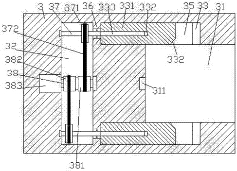
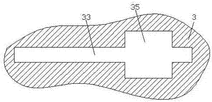
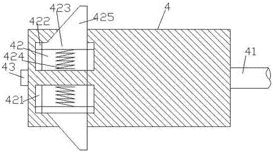
[0021] Such as Figure 1-Figure 7 As shown, a signal transmission device of the present invention includes a base 5, a column body 6 installed above the base 5, an assembly block 622, a signal transmission end 3 disposed in the assembly block 622, and a signal connector 4. There are suction cups 52 on the four corners of the bottom of the base 5. The suction cups 52 are used to absorb and fix the base 5, thereby increasing the stability during fixing. Slots 31 are provided, and lock slots 35 are arranged on the upper and lower inner walls of the slots 31. The inside of the lock slots 35 is provided with slide slots 33 extending to both sides. A cavity 32 is provided inside the signal transmission end 3, a partition plate 36 is provided between the cavity 32 and the left extension section of the chute 33, and a first steering wheel is provided at the midpoint of the cavity 32. Shaft 38, the cavity 32 on the upper and lower sides of the first steering shaft 38 is equally provid...


PUM


Abstract

The invention discloses a signal transmission device, which includes a base, a cylinder installed above the base, an assembly block, a signal transmission end arranged in the assembly block, and a signal connector. At the same time, four corners of the bottom of the base are provided with suction cups. The suction cup is used to absorb and fix the base. There is a slot in the right side of the signal transmission end. There are lock slots on the upper and lower inner walls of the slot. There are slide slots extending to both sides through the lock slot. There is a cavity in the signal transmission end on the left side, a partition plate is set between the cavity and the left extension of the chute, a first steering shaft is set at the midpoint of the cavity, and the upper and lower sides of the first steering shaft The second steering shaft extending to the left and right sides is equally installed in the cavity. The extension section on the right side of the second steering shaft passes through the partition plate and is connected with steering fit. A push plate is connected with a movable fit in the chute, and the left end surface of the push plate is A screw hole is provided inside, and the first stud is connected with the internal thread of the screw hole; the invention has the advantages of simple structure, convenient operation, high locking stability, and prevents clamping from loosening.

Description

technical field [0001] The invention relates to the field of information technology, in particular to a signal transmission device. Background technique [0002] With the rapid development of the information age, the use of computers is becoming more and more widespread. However, computers need to be connected to the network through a network cable before they can be used. The existing connection to the network is generally through the signal connection terminal (crystal plug). ) is clamped in the signal output hole to realize the connection work. Although the existing operation method of realizing the signal transmission work by clamping is simple, its clamping effect is not reliable, and it is very easy to be dragged and pulled by the network cable It will affect the loosening of the clamping connection, interrupt the signal transmission, and bring great inconvenience to the user. At the same time, the existing signal output hole is exposed to the outside when it is not cl...

Claims


Application Information

Patent Timeline
Patent Type & Authority Applications(China)
IPC IPC(8): H01R13/633H01R13/627H01R13/52
CPCH01R13/633H01R13/52H01R13/6275H01R2201/04H01R2201/06
Inventor 王海军
Owner 荆门市合方越达电子科技有限公司
Why Eureka
Try Eureka