Tourbillons, Movements and Clocks
A technology for tourbillons and clocks, which is applied in the field of tourbillons, movements and clocks. It can solve the problems of large-scale clocks and watches, difficulty in obtaining magnetic resistance, and difficulty in using magnetic materials to cover only tourbillons, etc., to achieve suppression of large-scale and excellent magnetic resistance. Effect
- Summary
- Abstract
- Description
- Claims
- Application Information
AI Technical Summary
Problems solved by technology
Method used
Image
Examples
no. 1 Embodiment approach >
[0052] [clock]
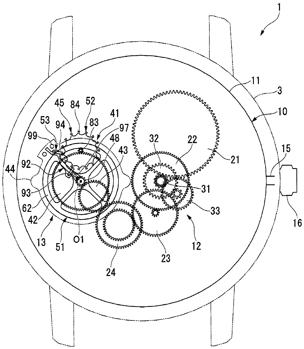
[0053] figure 1 It is an external view of the clock 1. In addition, in each drawing shown below, illustration of a part of each member is omitted for convenience of drawing, and each member is illustrated in a simplified form.
[0054] like figure 1 As shown, the timepiece 1 of this embodiment is constituted by incorporating a movement 10 in a timepiece case 3, a dial (not shown) having scales and the like displaying time-related information, various hands (not shown), etc. .
[0055] [movement]
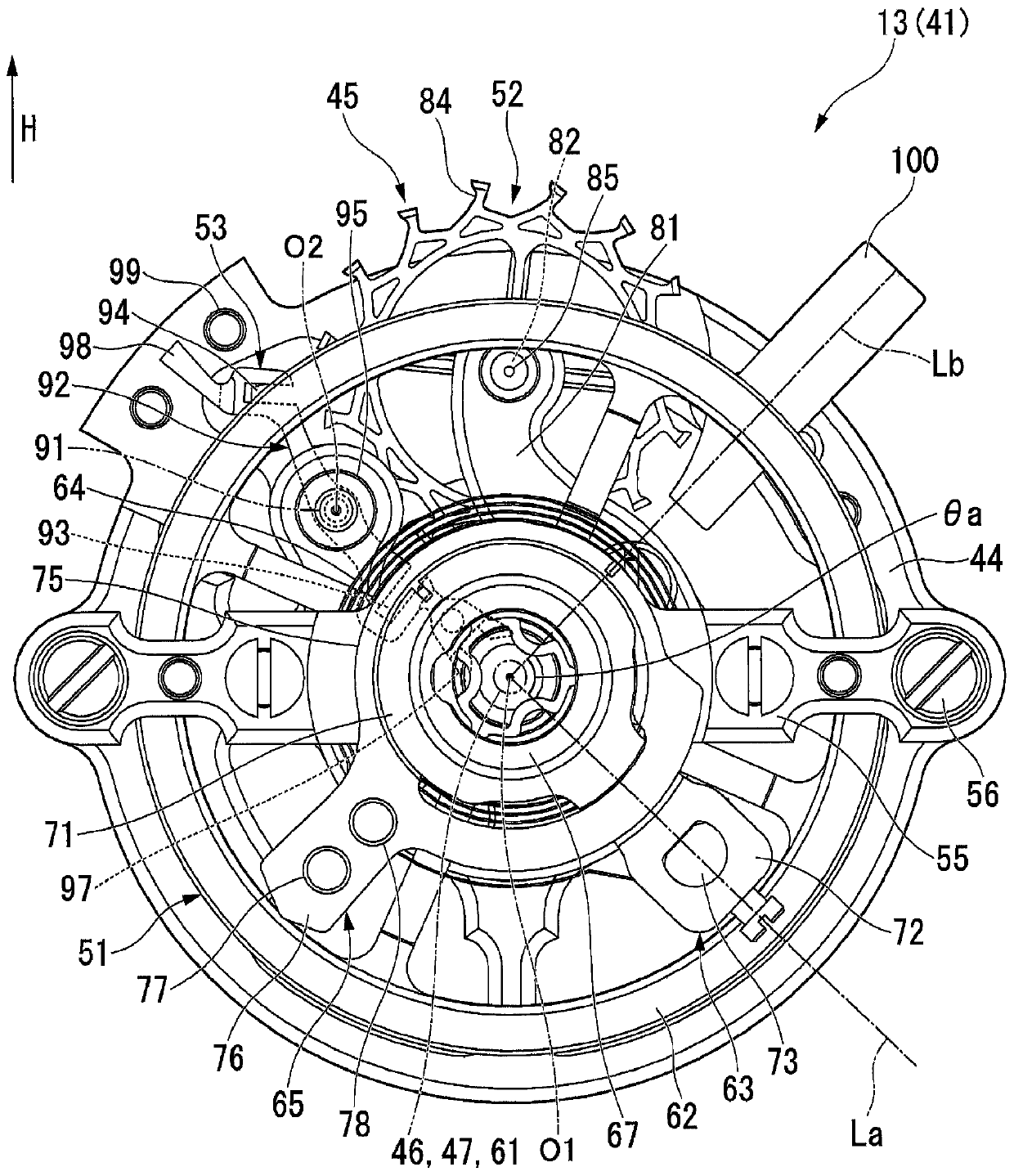
[0056] The movement 10 mainly has a base plate 11 , a front wheel train 12 and a tourbillon 13 . An arbor 15 is assembled in an arbor guide hole (not shown) of the base plate 11 . The stem 15 is rotatable about its axis and movable in the axial direction. In addition, a crown 16 located on the side of the timepiece case 3 is attached to one end portion of the stem 15 (a portion protruding from the movement 10 ). In addition, in the following description, the ...
no. 2 Embodiment approach >
[0132] Next, a second embodiment of the present invention will be described. Figure 13 It is a plan view of the frame unit 110 of the second embodiment. In addition, in the following description, the same code|symbol is attached|subjected to the same structure as said 1st Embodiment, and description is abbreviate|omitted.
[0133] exist Figure 13 In the frame unit 110 shown, the pallet fork body 92, the outer pile ring 63 and the speed needle 65 are all magnetic components. The pallet body 92 and the stud ring 63 are arranged such that the angle formed by the straight line connecting the radially outer end surface and the axis O1 becomes 180°.
[0134] In addition, the speed needle 65 is configured to form an angle of 90° with the pallet fork body 92 and the outer pile ring 63 respectively. In this case, the radially outer end surface of the jog needle arm 111 of the jog hand 65 is located radially outer than the frame bottom plate 44 .
[0135]Here, when the pallet body...
no. 3 Embodiment approach >
[0145] Next, a third embodiment of the present invention will be described. This embodiment differs from the above-described embodiment in that the axis centers of the frame shafts 46 and 47 are arranged at positions eccentric to the axis O1 of the frame bottom plate 44 . In addition, in the present embodiment, the stud ring 63 and the demagnetizing member 130 are magnetic members.
[0146] exist Figure 15 In the frame unit 131 shown, the frame shafts 46 and 47 are arranged on the same axis as the axis O2 of the pallet shaft 91 . Furthermore, a degaussing member 130 is provided on the balance with hairspring support 55 . The degaussing member 130 is formed in a plate shape extending in the radial direction.
[0147] Here, let the straight line connecting the radially outer end surface of the outer pile ring 63 (outer pile arm 72) and the axis O2 be the first straight line Lf, and let the straight line connecting the radially outer end surface of the degaussing member 100 a...
PUM
 Abstract
Description
Claims
Application Information
 - R&D
- Intellectual Property
- Life Sciences
- Materials
- Tech Scout
- Unparalleled Data Quality
- Higher Quality Content
- 60% Fewer Hallucinations
Browse by: Latest US Patents, China's latest patents, Technical Efficacy Thesaurus, Application Domain, Technology Topic, Popular Technical Reports.
© 2025 PatSnap. All rights reserved.Legal|Privacy policy|Modern Slavery Act Transparency Statement|Sitemap|About US| Contact US: help@patsnap.com


