A connection damping device for continuous girder bridges with hierarchical control and two-way seismic resistance

A shock absorbing device and hierarchical control technology, which is applied in bridges, bridge construction, bridge maintenance, etc., can solve the problems of unfavorable continuous girder bridge seismic performance, complicated maintenance in the later period, and small vertical stiffness, etc., and achieve good continuous energy consumption capacity and Effects of safety, elimination of additional seismic response, good deformation coordination

Active Publication Date: 2019-03-08
SHIJIAZHUANG TIEDAO UNIV
View PDF5 Cites 0 Cited by
  • Summary
  • Abstract
  • Description
  • Claims
  • Application Information

AI Technical Summary

Problems solved by technology

The Lock-up device uses the relative motion speed of the beam and pier as an index to determine the timing of locking. In theory, it can realize the coordinated force of each pier, but its high cost and complicated maintenance in the later period make its application less
Although some existing inventive devices can realize the locking function of the movable pier and the girder body and reduce the seismic response of the fixed pier and the girder body, due to the fixed connection stiffness, when the movable pier and the girder body are locked, the natural vibration period of the whole bridge will be shortened As a result, the overall seismic response of the whole bridge increases. In addition, due to the structural characteristics and the limitation of the mechanism, there is a gap in the existing locking device. Increasing the overall seismic response to a certain extent is not conducive to maximizing the aseismic performance of continuous girder bridges, and it is not easy to achieve energy dissipation and shock absorption
The above damping devices do not take into account the vertical seismic action. For long-span continuous girder bridges, due to the large span and small vertical stiffness, the impact of vertical seismic action on the bridge cannot be ignored

Method used


Image

  • A connection damping device for continuous girder bridges with hierarchical control and two-way seismic resistance
  • A connection damping device for continuous girder bridges with hierarchical control and two-way seismic resistance
  • A connection damping device for continuous girder bridges with hierarchical control and two-way seismic resistance

Examples


Embodiment Construction

[0049] In order to make the object, technical scheme and advantages of the present invention clearer, the following in conjunction with the attached Figure 1-16 The present invention is clearly and completely described with reference to specific examples.

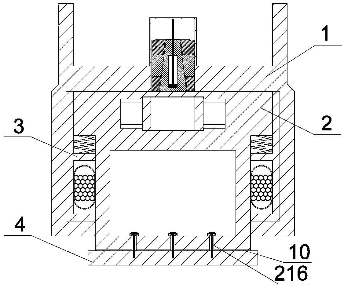
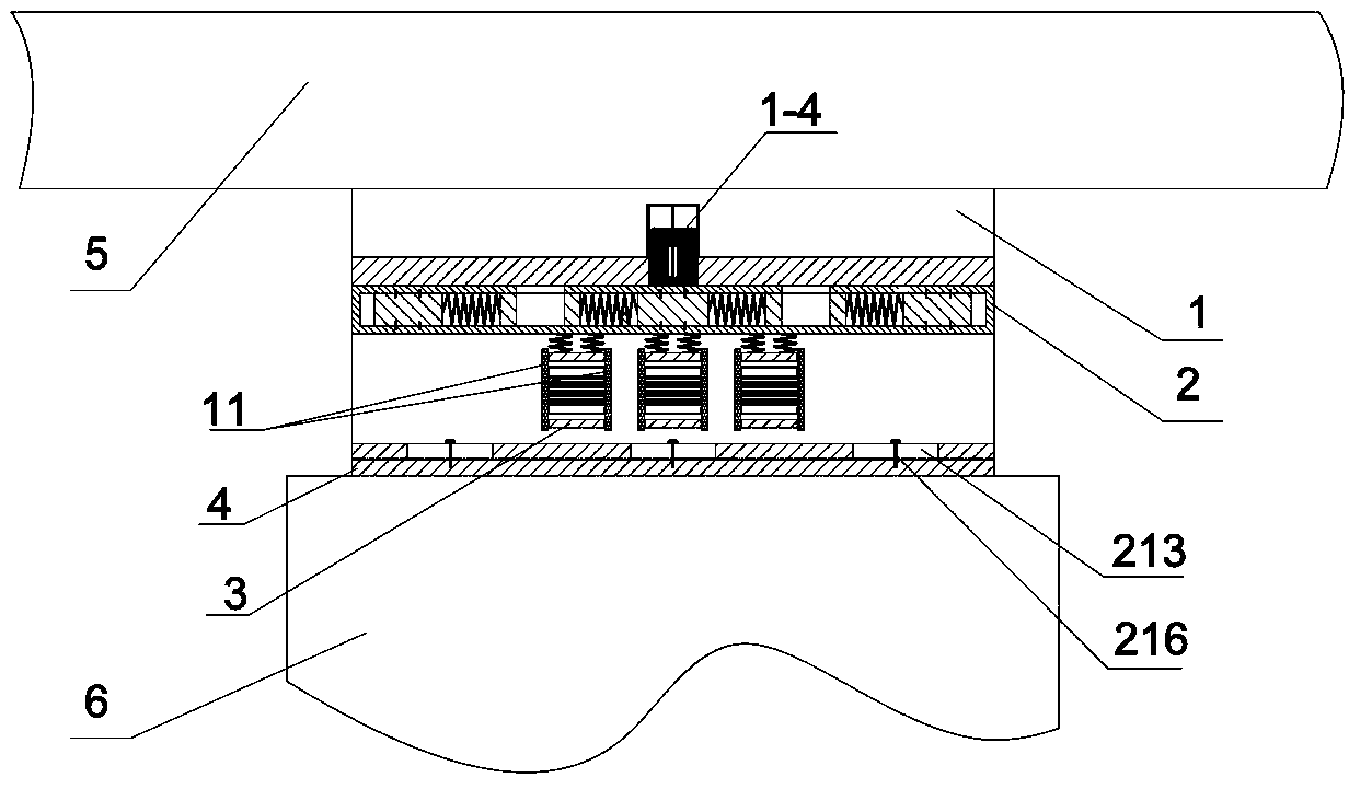
[0050] as attached figure 1 , 2 As shown, the present invention includes an upper slider 1, a lower slider 2, more than two inverted F-shaped members 3 and a bottom plate 4, and the bottom plate 4 is a rectangular steel plate. The top of the upper slider 1 is fixedly installed on the bottom of the beam body 5, the lower slider 2 is located in the lower part of the upper slider 1, the bottom of the lower slider 2 is fixed to the top of the bottom plate 4, and the bottom of the bottom plate 4 is fixedly installed At the top of the movable pier 6, a friction layer 10 is set between the bottom of the lower slider 2 and the top of the bottom plate 4, the maximum friction force that the friction layer 10 can bear is not greate...


PUM


Abstract

The invention relates to a continuous girder bridge graded control, two-way anti-seismic connection damping device, which includes an upper slider, a lower slider, more than two inverted F-shaped members and a bottom plate; the top of the upper slider is fixedly installed on the bottom of the beam body end, the lower slider is located in the lower part of the upper slider, the bottom of the lower slider is fixed to the top of the bottom plate, and a friction layer is set between the bottom of the lower slider and the top of the bottom plate. A large-tonnage continuous girder bridge damping device; the invention can provide new design concepts and technical ideas for the design of new bridges and the reinforcement of old bridges, and is suitable for new bridge construction and seismic reinforcement of old bridges.

Description

technical field [0001] The invention relates to a continuous girder bridge hierarchical control, two-way anti-seismic connecting shock absorbing device, which belongs to the field of bridge shock absorbing and isolating, and is suitable for the new anti-seismic design of highway bridges, railway bridges, urban bridges and various large continuous beam structures and existing Seismic reinforcement of buildings. Background technique [0002] In current highway bridges, railway bridges, urban bridges and various large-scale continuous beam structures, in order to meet the displacement requirements caused by temperature loads, each link of continuous beam bridges is often provided with only one fixed pier, which not only makes the seismic capacity of the fixed pier difficult It meets the seismic requirements, and also makes the longitudinal seismic displacement response of continuous girder bridges larger, which can easily cause damage to expansion joints and supports, and even ...

Claims


Application Information

Patent Timeline
Patent Type & Authority Patents(China)
IPC IPC(8): E01D19/00E01D19/04E01D22/00
CPCE01D19/00E01D19/04E01D22/00
Inventor 陈士通李锋许宏伟张耀辉孙志星逯久喜王海林
Owner SHIJIAZHUANG TIEDAO UNIV
Why Eureka
Try Eureka