Electric differential with directional torque distribution function

A technology for distributing functions and differentials. It is applied in the directions of differential transmissions, transmissions, belts/chains/gears, etc. It can solve the problem that the left and right output torque of the differential cannot be adjusted, so as to improve the turning maneuverability and reduce the layout. Space, compact structure

Active Publication Date: 2017-08-18
JILIN UNIV
View PDF5 Cites 0 Cited by
  • Summary
  • Abstract
  • Description
  • Claims
  • Application Information

AI Technical Summary

Problems solved by technology

[0005] The purpose of the present invention is to solve the defect that the left and right output torques of the differential are equal and cannot be adjusted, and provide an electric differential with a torque-oriented distribution function

Method used


Image

  • Electric differential with directional torque distribution function
  • Electric differential with directional torque distribution function
  • Electric differential with directional torque distribution function

Examples


Embodiment 1

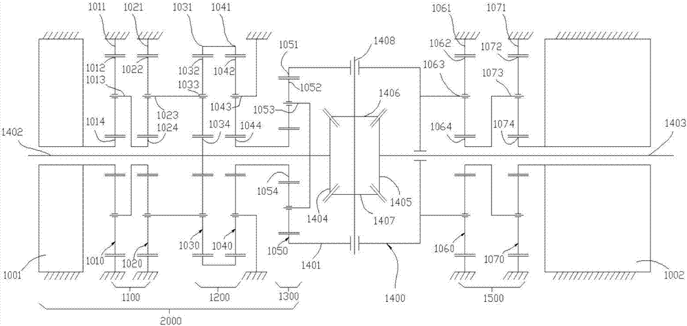
[0059] Such as figure 1 As shown, the present invention provides an electric differential with a torque distribution function, which is mainly composed of a torque directional distributor 2000, a traditional bevel gear differential 1400, a main drive motor reduction mechanism 1500 and a main drive motor 1002 .

[0060] In this embodiment, the torque directional distributor 2000 is located on the left side of the driving axle (it can also be exchanged with the main driving motor 1002, and it is arranged on the right side of the driving axle), and the TV control motor 1001 and the TV reduction mechanism are mainly used. 1100, double planetary row TV coupling mechanism 1200 and single planetary row differential coupling mechanism 1300 constitute.

[0061] The TV control motor 1001 is a hollow shaft inner rotor motor, the first half shaft 1402 connected to the left wheel passes through the inner hole of the hollow rotor shaft, the hollow shaft inner rotor and the sun gear of the ...

Embodiment 2

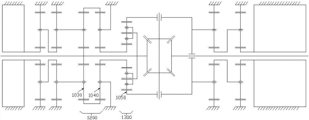
[0071] Such as figure 2 As shown, in this embodiment, the first planetary gear train 1030 and the second planetary gear train 1040 in the double planetary row TV coupling mechanism 1200 are both single planetary gear planetary row, and the first planetary gear train 1040 in the single planetary row differential coupling mechanism 1300 The three-planetary gear train 1050 is a two-stage planetary gear planetary row, and its structure is as shown in the figure.

Embodiment 3

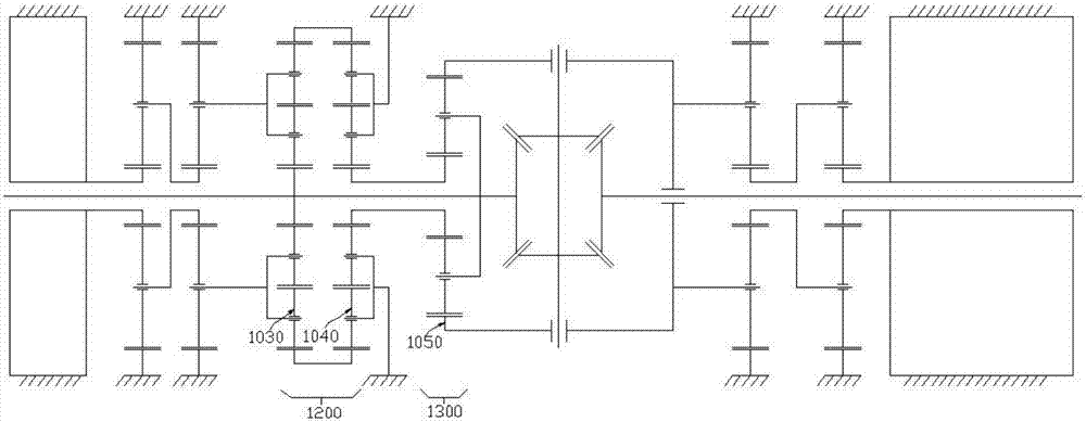
[0073] Such as image 3 As shown, in this embodiment, the first planetary gear train 1030 and the second planetary gear train 1040 in the double planetary row TV coupling mechanism 1200 are both double-stage planetary gear planetary rows, and the single planetary row differential coupling mechanism 1300 The third planetary gear train 1050 is a single planetary gear planetary row, and the schematic structure is as shown in the figure.


PUM


Abstract

The invention discloses an electric differential with a directional torque distribution function. The electric differential comprises a main driving mechanism, a bevel gear differential, a TV control driving mechanism, a first single-row planetary gear train, a second single-row planetary gear train and a third single-row planetary gear train, wherein the TV control driving mechanism is used for outputting control power; a first sun wheel and a first half shaft are coaxially and fixedly connected, and a first planetary carrier is connected with the control output end; a second planetary carrier is fixed to a driving axle shell, and a second gear ring is fixedly connected with a first gear ring; a second sun wheel is supported on the first half shaft through a bearing; a third sun wheel is fixedly connected with the second sun wheel, a third planetary carrier is fixedly connected with the first half shaft, and a third gear ring is fixedly connected with a differential shell; and the second single-row planetary gear train and the first single-row planetary gear train have the same characteristic parameters. According to the electric differential, the driving torque of an automobile can be distributed to wheels on the left side and the right side in a directional mode according to control requirements of the control logic.

Description

technical field [0001] The invention belongs to the technical field of electric vehicle transmission, and in particular relates to an electric differential with torque orientation distribution function. Background technique [0002] Due to the energy crisis and the increasing emphasis on environmental protection, new energy vehicles are the reverse of the development of future vehicles, and electric vehicles have achieved rapid development worldwide. Compared with traditional internal combustion engine vehicles, electric vehicles are more economical and environmentally friendly, and the characteristics of nearly zero emissions make electric vehicles have significant advantages in environmental protection. At the same time, electric vehicles have better acceleration performance due to the characteristics of fast response of the drive motor, low speed and high torque, and the motor speed and torque are easy to obtain, which can control the electric vehicle more precisely. The...

Claims


Application Information

Patent Timeline
IPC IPC(8): F16H48/06F16H48/38
CPCF16H48/06F16H48/38
Inventor 王军年杨斌
Owner JILIN UNIV
Why Eureka
Try Eureka