A method for non-destructive evaluation of damage performance of optical components

A technology for optical components and performance, applied in the field of non-destructive evaluation of optical components, can solve problems such as small scale, laser output improvement, optical component damage, etc., to achieve the effect of damage performance

Inactive Publication Date: 2018-12-18
LASER FUSION RES CENT CHINA ACAD OF ENG PHYSICS
View PDF8 Cites 0 Cited by
  • Summary
  • Abstract
  • Description
  • Claims
  • Application Information

AI Technical Summary

Problems solved by technology

[0002] The problem of optical component damage has always been a key issue in the development of large-scale high-power / high-energy laser devices, which determines the maximum output capability of laser devices and limits the further improvement of laser output
[0004] At present, the commonly used optical component testing methods are mainly surface shape, stress, surface roughness, defect, transmittance, etc. Research shows that the test results of these methods have no direct relationship with the damage performance of optical components, but are directly related to subsurface microscopic defects. Below the surface, extremely small and difficult to detect

Method used


Image

  • A method for non-destructive evaluation of damage performance of optical components
  • A method for non-destructive evaluation of damage performance of optical components
  • A method for non-destructive evaluation of damage performance of optical components

Examples


Embodiment 1

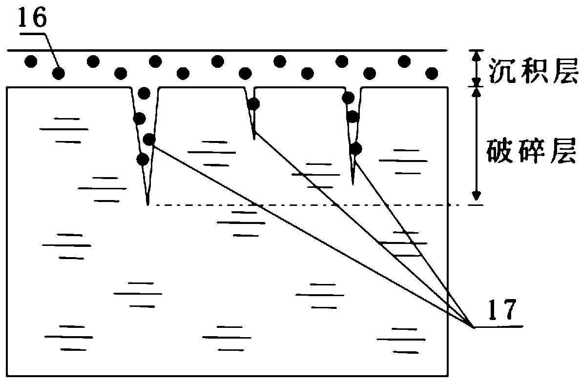
[0029] Embodiment 1: see figure 1 , the surface of sample 5 is divided into a sedimentary layer and a broken layer. The surface of the sedimentary layer is polished, and there are many microcracks 17 in the broken layer below it. Both the sedimentary layer and the broken layer contain impurities 16. Based on the damage mechanism of the optical element, that is, the subsurface microcracks 17 embedded in the polluting impurities 16 are easy to absorb high-flux laser energy to cause damage under laser irradiation. For the buried polluting impurities 16, the corresponding fluorescent defects are obtained by detecting the fluorescence emitted by them.

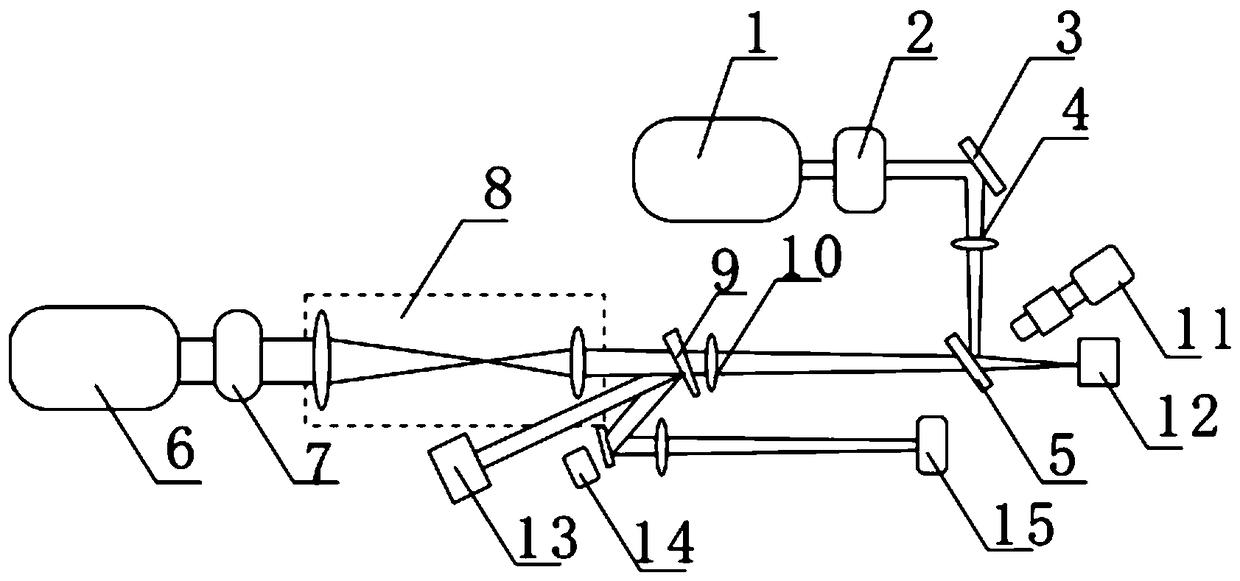
[0030] see figure 2 and image 3 , in order to test, must use optical path system, we construct a kind of optical path system for the present invention, described optical path system comprises continuous laser 1, pulsed laser 6, sample stage, microscopic imaging system 11, sample stage can move three-dimensionally And the sample...


PUM


Abstract

The invention discloses a method for realizing lossless evaluation for damage performance of an optical element. A continuous laser device can transmit continuous laser. After a first energy regulator, a first lens, a reflector and the front surface of a sample, the continuous laser is irradiated to the back surface of the sample. The reflecting direction of the continuous laser after reflection by the sample is provided with a residual laser collector. The pulse laser can transmit pulse laser. After a second energy regulator, a beam compressing system, a split board and a second lens, the pulse laser is irradiated to the back surface of the sample. According to the method of the invention, multiple-sample and multiple-position testing is performed on the elements which are same with a to-be-tested optical element for obtaining a correlation relation between fluorescent defect data and a laser damage threshold and a damage density in the optical elements of this kind, thereby calculating the damage threshold and the damage density in measurement of the to-be-tested sample through measuring the fluorescent defect data. According to the method of the invention, a damage performance level of the optical element can be obtained through lossless testing for the fluorescent defect of the optical element, thereby realizing lossless evaluation to the damage performance of the optical element.

Description

technical field [0001] The invention relates to a non-destructive evaluation method of an optical element, in particular to a method for non-destructive evaluation of the damage performance of an optical element. Background technique [0002] The damage of optical components has always been a key issue in the development of large-scale high-power / high-energy laser devices, which determines the maximum output capability of laser devices and limits the further improvement of laser output. In order for a laser device to operate safely at the maximum output flux possible, it is extremely important to evaluate the damage performance of optical components before they are put into shelf use. At present, the evaluation of the damage performance of optical components is realized by directly performing damage tests on the components. The most direct and accurate results can be obtained through the damage test, but the damage test itself is a consuming process, and the tested componen...

Claims


Application Information

Patent Timeline
Patent Type & Authority Patents(China)
IPC IPC(8): G01M11/02G01N21/64
CPCG01M11/00G01N21/6402
Inventor 刘红婕蒋晓东王凤蕊黄进耿峰叶鑫孙来喜黎维华罗青
Owner LASER FUSION RES CENT CHINA ACAD OF ENG PHYSICS
Why Eureka
Try Eureka