
Filter press protective cover

A technology of protective cover and filter press, applied in the direction of filtration and separation, separation methods, chemical instruments and methods, etc., can solve the problems that cannot be easily opened at any time, operation is not very convenient, and has no effect, so as to achieve convenient observation work Progress, light weight, time-saving effect

Inactive Publication Date: 2017-08-22
苏子战
View PDF4 Cites 3 Cited by
  • Summary
  • Abstract
  • Description
  • Claims
  • Application Information

AI Technical Summary

Problems solved by technology

[0004] At present, due to different standards, the filter presses demanded abroad have more requirements than the domestic filter presses. The machine is equipped with a protective cover to effectively protect the personal safety of the operator, but the protective cover of the filter press produced today is basically fixed on the filter press body with screws, and cannot be opened at any time conveniently. When it is necessary to replace or When repairing the parts in the protective cover of the filter press, or removing foreign matter and cleaning the parts, it is necessary to remove the protective cover, and you need to loosen the screws to remove the protective cover. The operation is not very convenient, and it is time-consuming and laborious, which will affect the production efficiency. Even if the two sides of some shields are equipped with sliding door structures, when it is necessary to lift all the filter devices or replace large and heavy parts, it is necessary to remove the protective cover fixed on the top of the filter press, which also requires more work. time, and it is inconvenient to operate
In addition, the length of the protective cover that comes with the current filter press is basically as long as the protective frame, and some parts do not play a role, wasting materials and increasing costs

Method used


Image

  • Filter press protective cover
  • Filter press protective cover
  • Filter press protective cover

Examples


Embodiment Construction

[0020] The technical solutions of the present invention will be described in detail below in conjunction with examples. The following examples are only used to illustrate the technical solutions of the present invention more clearly, and therefore are only examples, rather than limiting the protection scope of the present invention.

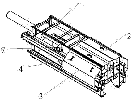
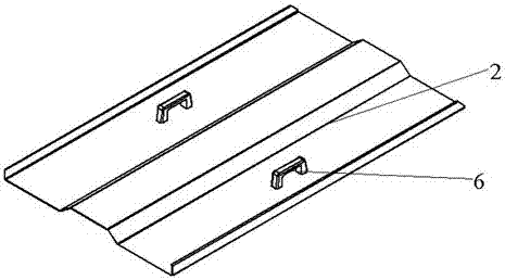
[0021] Such as Figure 1-4 The filter press protective cover in the shown embodiment includes a protective frame 1 , a top door protective cover 2 , and a side sliding door protective cover 3 . There are four protective frames 1 in total, each of which is made of stainless steel, and its shape is a combination of triangle iron type and groove type. There are screw holes 5 and limit blocks 4 at both ends. The material of limit block 4 is rubber, and the top door protective cover 2 and The integral material of side sliding door protective cover 3 is plexiglass, handle 6 is all arranged above, the length of top door protective cover 2 and side slid...


PUM


Abstract

The present invention belongs to the technical field of filter press, and more specifically, relates to a filter press protective cover. The protective cover includes a frame, the frame is fixed on the top and bottom of the filter press with screws, the top door protective cover is placed on the protective frame on the top of the filter press, and the side sliding door protective cover is placed on the protective frame on the side of the filter press. , the length of the top door protection cover and the side sliding door protection cover is customized according to the length of the filter device when it is compressed. The top door protection cover and the side sliding door protection cover can be slid or removed. There are stoppers at both ends of the protection frame to prevent the protection cover from Falling off, damaging the filter press or self-destructing, there are handles on the protective cover, the material is plexiglass, and the weight is very light, the protective cover is placed on the protective frame, the operation is very convenient, it will save a lot of time and improve work efficiency , and strong portability.

Description

technical field [0001] The invention belongs to the field of filter presses of filter equipment, and more specifically relates to a filter press protective cover. [0002] technical background [0003] The filter press is a low-energy, high-efficiency intermittent pressurized filtration equipment used for solid-liquid separation of various slurries. It relies on a compacting device to compress the filter plate, and then pumps the slurry into the filter The filter cloth is used to separate the solid particles from the liquid, and it is widely used because of its large filtration area and high efficiency. Especially in the solid-liquid separation industry, the filter press is the main filtering equipment, which has a long history of being used in industrial production. It has good separation effect and strong adaptability, especially for the separation of viscous and fine materials, it has its unique advantages. , The plate and frame filter plate is the main filter element of ...

Claims


Application Information

Patent Timeline
Patent Type & Authority Applications(China)
IPC IPC(8): B01D25/12
CPCB01D25/12
Inventor 苏子战
Owner 苏子战
Learn More