Supercharge Your Innovation With Domain-Expert AI Agents!

Direct current ventilation and heat dissipation type electric heater

A technology of ventilation and heat dissipation, electric heater, applied in the direction of fluid heater, air heater, lighting and heating equipment, etc., can solve the problems of unsatisfactory ventilation and heat dissipation effect, poor heat dissipation effect, increased material cost, etc. and ventilation effect optimization, eliminate the limitations of production height, improve the effect of profit margins

Inactive Publication Date: 2017-08-22
YIXING CITY GUANGTONG ELECTROMECHANICAL EQUIPCO
View PDF0 Cites 0 Cited by
  • Summary
  • Abstract
  • Description
  • Claims
  • Application Information

AI Technical Summary

Problems solved by technology

[0003] 1. Since the air inlet and outlet of the electric heater are horizontal, the wind will accumulate inside the electric heater, and the ventilation and heat dissipation effect is not very ideal;
[0004] 2. In order to ensure the ventilation effect, there must be enough space inside the electric heater, so the height of the electric heater must be high, because once the height is low and the internal space is small, the

Method used


Image

  • Direct current ventilation and heat dissipation type electric heater
  • Direct current ventilation and heat dissipation type electric heater
  • Direct current ventilation and heat dissipation type electric heater

Examples


Embodiment 1

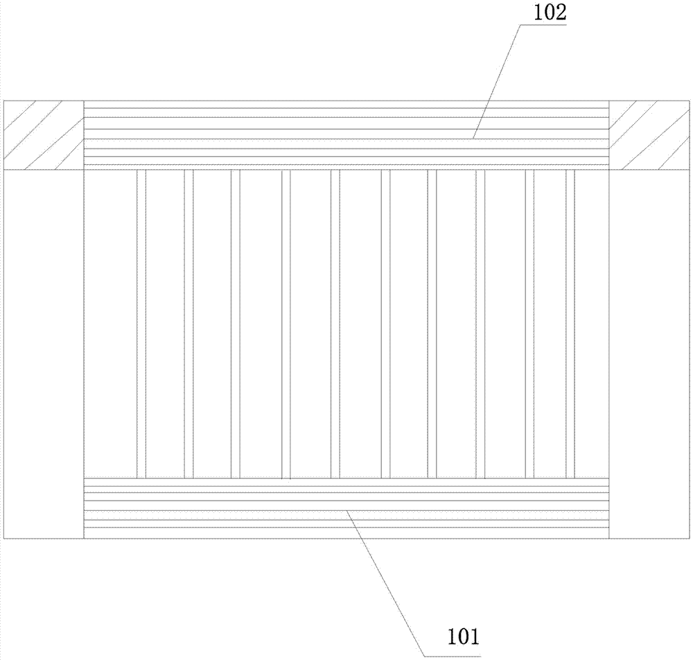
[0028] Such as Figure 3-Figure 7 As shown, the present invention provides a direct current ventilation and heat dissipation electric heater, comprising a hollow heat dissipation shell 7 and a heating pipe 3 located in the hollow heat dissipation shell 7, and a plurality of heat dissipation fins 4 uniformly arranged in a horizontal direction are arranged in the hollow heat dissipation shell 7, The heating pipe 3 runs through all the cooling fins 4, and the top and bottom surfaces of the hollow heat dissipation shell 7 are respectively provided with an upper ventilation grille window 121 and a lower ventilation grille window 221, and the lower ventilation grille window 221 is located on the upper ventilation grille window. Directly below the grille window 121, the heat sink 4 is located between the upper ventilation grille window 121 and the lower ventilation grille window 221, and both ends of the hollow heat dissipation shell 7 are welded and encapsulated by a plastic packagin...

Embodiment 2

[0030] The wind enters the hollow heat dissipation shell 7 from the lower ventilation grille window 221 at the bottom of the hollow heat dissipation shell 7 and keeps the original wind direction and passes through the heat sink 4 and the heat pipe 3 through the space between the adjacent heat sinks 4, and finally from The upper ventilation grille window 121 flows out, and the wind direction maintains a direct current mode during the whole process, and the wind force and wind speed can be maintained. The ventilation and heat dissipation performance in the hollow heat dissipation shell 7 is very good.


PUM


Abstract

The invention discloses a direct current ventilation and heat dissipation electric heater, which comprises a hollow heat dissipation shell and a heating pipe located in the hollow heat dissipation shell. A plurality of heat dissipation fins uniformly arranged in the horizontal direction are arranged in the hollow heat dissipation shell, and the heat dissipation pipe runs through all heat dissipation The top surface and the bottom surface of the hollow heat dissipation shell are respectively provided with an upper ventilation grille window and a lower ventilation grille window, and the lower ventilation grille window is located directly below the upper ventilation grille window. The present invention adopts the direct current air inlet and outlet mode without changing the flow direction of the wind, and the wind force and wind speed have been significantly improved compared with the existing horizontal air inlet and outlet methods, and the ventilation and heat dissipation effect of the electric heater has been improved. Substantially improved.

Description

technical field [0001] The invention relates to an electric heater, in particular to a direct current ventilation and heat dissipation electric heater. Background technique [0002] An existing electric heater such as figure 1 As shown, the air inlet layer 101 and the air outlet layer 102 are all arranged on the front or back of the electric heater, and the wind enters the inside of the electric heater from the air inlet layer 101 and then comes out from the air outlet layer 102, thereby realizing the effect of ventilation and heat dissipation, but The structural design of this kind of ventilation has the following disadvantages: [0003] 1. Since the air inlet and outlet of the electric heater are horizontal, the wind will accumulate inside the electric heater, and the ventilation and heat dissipation effect is not very ideal; [0004] 2. In order to ensure the ventilation effect, there must be enough space inside the electric heater, so the height of the electric heater ...

Claims


Application Information

Patent Timeline
IPC IPC(8): F24H3/00F24H9/02F24H9/18F24H9/00F24H9/20F24H9/06
CPCF24H3/002F24H9/0063F24H9/02F24H9/06F24H9/1863F24H9/2071F24H2250/02
Inventor 王海兴韩学雷
Owner YIXING CITY GUANGTONG ELECTROMECHANICAL EQUIPCO
Features
  • R&D
  • Intellectual Property
  • Life Sciences
  • Materials
  • Tech Scout
  • Unparalleled Data Quality
  • Higher Quality Content
  • 60% Fewer Hallucinations
Learn More