Pneumatic tire

A pneumatic tire, tire technology, applied in tire parts, tire tread/tread pattern, transportation and packaging, etc., to achieve superior wet performance, prevent rigidity from being reduced, and superior ride comfort.

Active Publication Date: 2017-09-12
SUMITOMO RUBBER IND LTD
View PDF9 Cites 13 Cited by
  • Summary
  • Abstract
  • Description
  • Claims
  • Application Information

AI Technical Summary

Problems solved by technology

[0003] However, the above-mentioned pneumatic tires

Method used


Image

  • Pneumatic tire
  • Pneumatic tire
  • Pneumatic tire

Examples


Example Embodiment

[0031] Hereinafter, an embodiment of the present invention will be described based on the drawings.

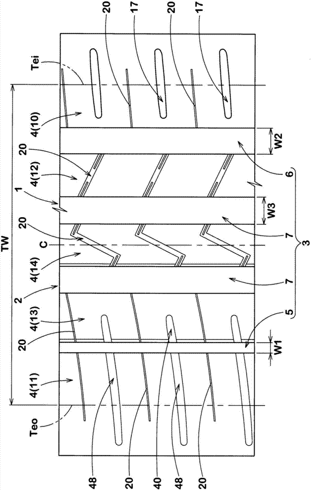
[0032] figure 1 It is a development view of the tread portion 2 of the pneumatic tire 1 of the present embodiment. The pneumatic tire 1 of the present embodiment is preferably implemented as a passenger car, for example.

[0033] The tread portion 2 of the present embodiment has a tread pattern in which the direction of mounting to the vehicle is specified. The direction of mounting to the vehicle is indicated on the sidewall portion with characters or marks (illustration omitted), for example.

[0034] Such as figure 1 As shown, the tread portion 2 has an outer tread end Teo located outside the vehicle when the vehicle is installed, and an inner tread end Tei located inside the vehicle when the vehicle is installed.

[0035] The outer tread end Teo and the inner tread end Tei are respectively defined as the outermost ground contact positions in the tire axial direction when a normal...


PUM


Abstract

A pneumatic tire comprises a tread portion 2 having an outside tread edge Teo and an inside tread edge Tei to be positioned outside and inside, respectively, with respect to a vehicle. The tread portion 2 is axially divided into land regions 4 by four main grooves 3 including an outside shoulder main groove 5, an inside shoulder main groove 6 and two crown main grooves 7. The outside shoulder main groove 5 has a width smaller than the inside shoulder main groove 6 and the crown main grooves 7. The land portions 4 include an inside shoulder land region 10 provided with inside shoulder lateral grooves 17. Each of the land regions 4 is provided with sipes 20 each extending across the entire width of the land region and having a width less than 3 mm.

Description

technical field [0001] The present invention relates to a pneumatic tire capable of improving wet performance, steering stability, and riding comfort in a balanced manner. Background technique [0002] For example, Patent Document 1 below proposes a pneumatic tire having a tread portion mounted on a vehicle with a designated orientation. In the pneumatic tire of Patent Document 1, the inner shoulder land portion positioned on the inner side of the vehicle when mounted on the vehicle has lug grooves extending from the tread end toward the inner side in the tire axial direction and terminating in the inner shoulder land portion. The aforementioned lug grooves can prevent a decrease in the rigidity of the inner shoulder land portion and improve drainage. [0003] However, the above-mentioned pneumatic tires have room for further improvement in riding comfort. [0004] Patent Document 1: Japanese Unexamined Patent Publication No. 2013-224132 Contents of the invention [000...

Claims


Application Information

Patent Timeline
IPC IPC(8): B60C11/03B60C11/12
CPCB60C11/0304B60C11/0323B60C11/1204B60C11/1236B60C2011/1227B60C11/0306B60C11/1263B60C2011/0353B60C2011/0365B60C2011/0369B60C2011/1209B60C11/124
Inventor 早苗隆平
Owner SUMITOMO RUBBER IND LTD
Why Eureka
Try Eureka