MIMO (Multiple-Input Multiple-Output) wireless channel modeling method fusing smart antenna

A smart antenna and wireless channel technology, applied in the field of MIMO wireless channel modeling that integrates smart antennas, can solve problems such as no longer applicable, and achieve the effect of simplifying the channel structure

Active Publication Date: 2017-09-15
UNIV OF ELECTRONICS SCI & TECH OF CHINA
View PDF3 Cites 6 Cited by
  • Summary
  • Abstract
  • Description
  • Claims
  • Application Information

AI Technical Summary

Problems solved by technology

Obviously, for this special MIMO structure, the existi

Method used


Image

  • MIMO (Multiple-Input Multiple-Output) wireless channel modeling method fusing smart antenna
  • MIMO (Multiple-Input Multiple-Output) wireless channel modeling method fusing smart antenna
  • MIMO (Multiple-Input Multiple-Output) wireless channel modeling method fusing smart antenna

Examples


Embodiment Construction

[0045] In order to make the purpose, technical solution and advantages of the present invention clearer, the present invention will be further described in detail below in conjunction with the implementation methods and accompanying drawings.

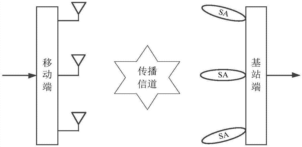
[0046] The embodiment simulates the transmission environment of the communication uplink (transmitting at the mobile end-receiving at the base station end), and its channel space structure is as follows: figure 1 shown. Wherein, the mobile terminal (MS) sends information with M=3 omnidirectional antennas arranged uniformly and linearly, and the normalized distance between adjacent antennas is 8. The base station (BS) uses N=3 smart antenna beams to receive information in a directional manner, and the 3 smart antennas are equally spaced (the normalized spacing is 5) and arranged linearly, and each smart antenna has a normalized array element spacing of 0.5 , the number of array elements is K i =3 uniform linear array. The antenna at t...


PUM


Abstract

The invention discloses an MIMO (Multiple-Input Multiple-Output) wireless channel modeling method fusing a smart antenna, and belongs to the technical field of wireless communication. The method comprises the following steps: firstly, constructing a transmitting end antenna correlation matrix and a receiving end wave beam correlation matrix, and taking a Kronecker product of the transmitting end antenna correlation matrix and the receiving end wave beam correlation matrix as an integral correlation matrix; taking a matrix obtained through Cholesky decomposition of the integral correlation matrix as a spatial correlation forming matrix; generating a spatial independent MIMO channel fading coefficient; allocating power to different delay paths according to power delay distribution of a channel; calculating a channel coefficient matrix of all delay paths according to a time-frequency fading characteristic of an MIMO channel and the spatial correlation forming matrix; and lastly, building an MIMO wireless channel matrix fusing the smart antenna according to the channel coefficient matrix and path delays of all the delay paths according to a tapped delay line structure of a frequency selective channel. Through implementation of the method, a propagation channel of an actual MIMO-smart antenna fusion system can be approximated well.

Description

technical field [0001] The invention relates to the technical field of wireless communication, in particular to a MIMO wireless channel modeling method integrating smart antennas. Background technique [0002] MIMO (Multiple-Input Multiple-Output) technology, as a key technology in the new generation of mobile communication, has shown great advantages in improving the capacity and reliability of wireless communication systems. With the help of a sufficiently scattered propagation environment, the MIMO system can establish parallel transmission sub-channels, and double the capacity and reliability of the communication system without increasing the system bandwidth and transmission power. [0003] The performance of the MIMO system is greatly affected by the wireless propagation environment. Therefore, understanding and mastering the characteristics of MIMO channels in various transmission environments is very important for realizing the potential huge channel capacity of the ...

Claims


Application Information

Patent Timeline
IPC IPC(8): H04B17/391H04B7/0413
CPCH04B7/0413H04B17/3912
Inventor 郑植郑彦吴玉婕杨海芬
Owner UNIV OF ELECTRONICS SCI & TECH OF CHINA
Why Eureka
Try Eureka