
Radar navigation communication antenna with function of searching and receiving signal by spiral lifting

A technology for receiving signals and radar navigation, applied in the field of communication antennas, can solve the problems of poor stability of manual adjustment of height, difficult to grasp the adjustment range of height, poor signal reception effect, etc., and achieves good signal reception effect, good motion stability, and improved The effect of smoothness

Inactive Publication Date: 2017-09-26
苏炎杰
View PDF0 Cites 0 Cited by
  • Summary
  • Abstract
  • Description
  • Claims
  • Application Information

AI Technical Summary

Problems solved by technology

[0004] In order to solve the above problems, the present invention provides a radar navigation communication antenna with a spiral lift to search and receive signals, which can solve the problems of manual adjustment of the radar antenna signal receiving height, such as difficulty in grasping the adjustment height range, poor stability of manual adjustment height, and radar antenna failure. There are problems such as errors between the azimuth angle and the azimuth angle of the radar transmission signal, and poor signal reception. It can realize the stable automatic spiral lifting search signal function of the radar antenna. The radar antenna can be accurately adjusted to the required signal receiving height, and the spiral lifting adjustment process is stable. Well, the signal reception effect is good, and it provides a new way of high-efficiency radar antenna signal conditioning

Method used


Image

  • Radar navigation communication antenna with function of searching and receiving signal by spiral lifting
  • Radar navigation communication antenna with function of searching and receiving signal by spiral lifting
  • Radar navigation communication antenna with function of searching and receiving signal by spiral lifting

Examples


Embodiment Construction

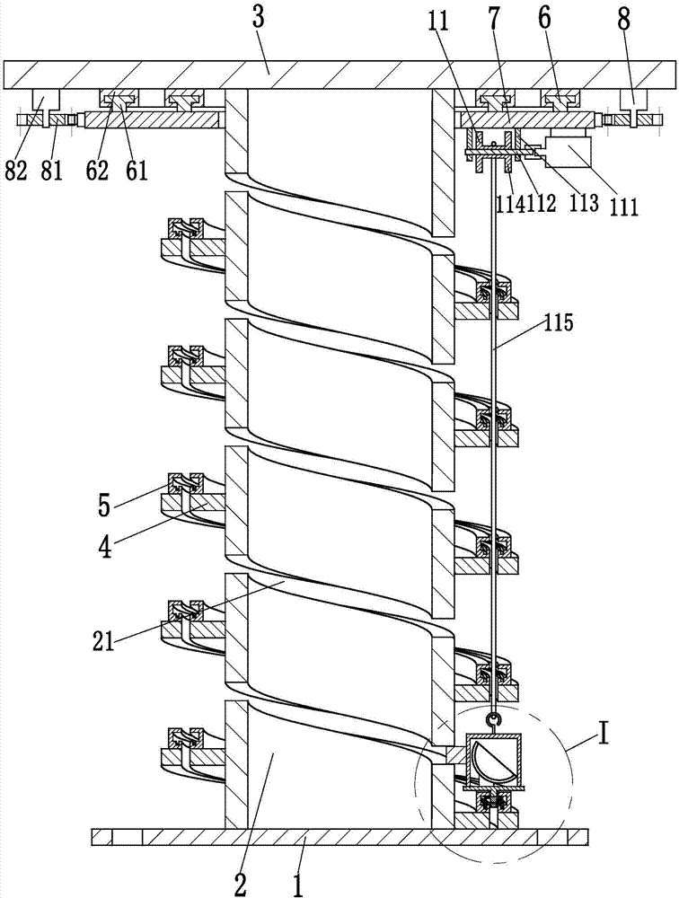
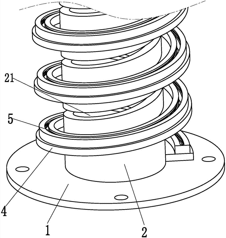
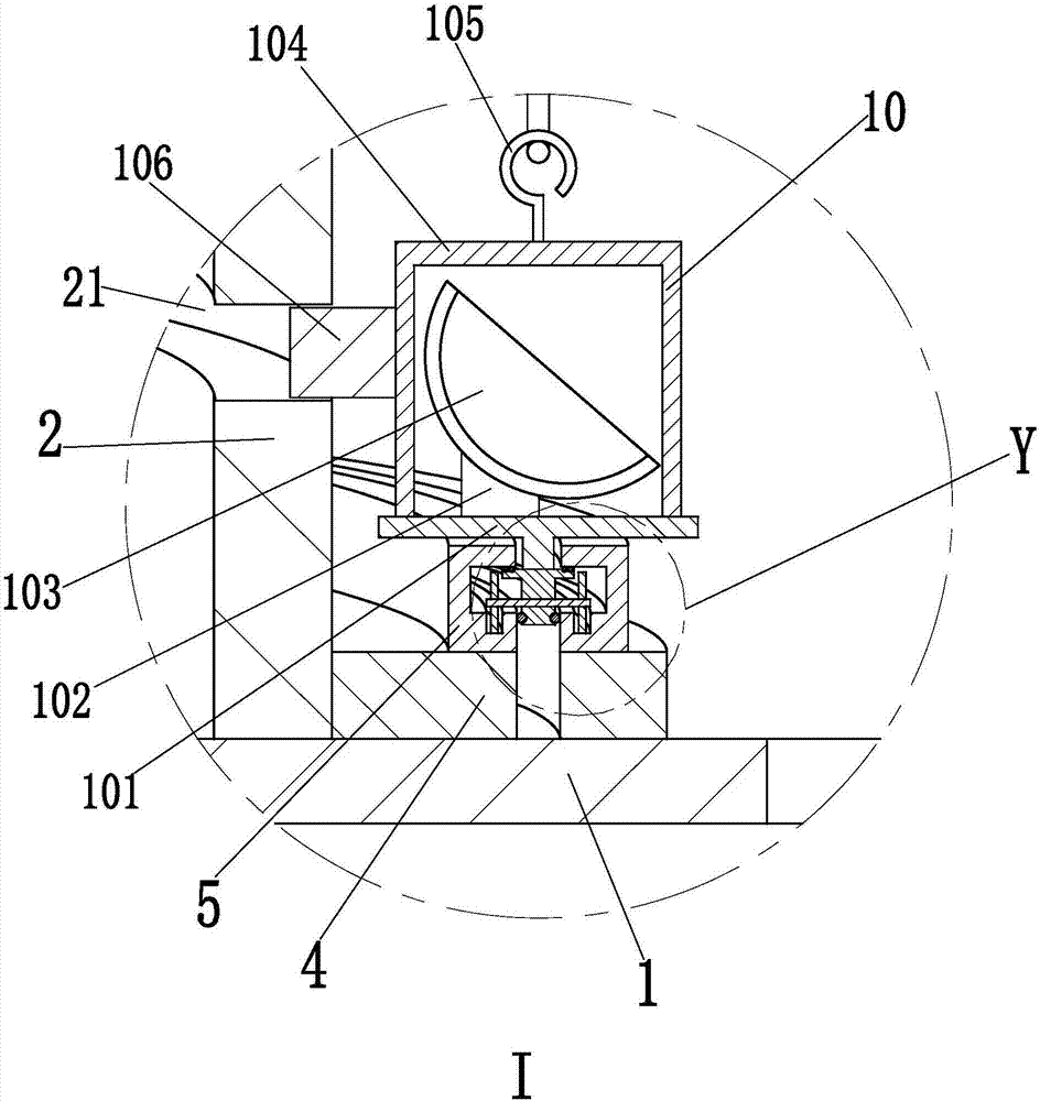
[0028] In order to make the technical means, creative features, goals and effects achieved by the present invention easy to understand, the present invention will be further described below in conjunction with specific illustrations.

[0029] Such as Figure 1 to Figure 4 As shown, a radar navigation communication antenna with a spiral lifting search for receiving signals includes a base 1, a base frame 2 of a hollow cylindrical structure is welded on the base 1, and a base cover 3 is welded on the top of the base frame 2; The base frame 2 is provided with a guide groove 21 in a spiral structure from bottom to top, and the outer wall of the base frame 2 is installed with a support sheet 4 in a spiral structure from bottom to top, and the middle part of the support sheet 4 is provided with a lower threading guide groove in a spiral structure. groove, and the start and end of the support sheet 4 are in a closed structure, the support sheet 4 is provided with a guide chute 5 in a...


PUM


Abstract

The invention relates to a radar navigation communication antenna with a spiral lift to search and receive signals, comprising a base, a base frame is welded on the base, and a base cover is welded on the top of the base frame; the base frame is provided with a guide groove in a spiral structure from bottom to top , the outer wall of the base frame is installed with a support sheet in a spiral structure from bottom to top, and a guide chute in a spiral structure is arranged on the support sheet; the lower end of the base cover is equipped with a ring-shaped guide mechanism, and the lower end of the ring-shaped guide mechanism is installed with a rotating gear, the left and right ends of the rotating gear are meshed with a driving mechanism; a sliding mechanism is installed in the guide chute, and an antenna mechanism is installed on the sliding mechanism; a winding mechanism is installed on the lower end of the rotating gear, and the driving mechanism, rotating gear, The circular guiding mechanism, winding mechanism, sliding mechanism and the antenna mechanism cooperate to complete the spiral lifting and guiding process of the antenna mechanism. The invention can realize the stable automatic spiral lifting search signal function of the radar antenna.

Description

technical field [0001] The invention relates to the technical field of communication antennas, in particular to a radar navigation communication antenna with a spiral lift to search and receive signals. Background technique [0002] The antenna is a converter whose main function is to transform the guided wave propagating on the transmission line into electromagnetic waves propagating in the unbounded medium. Antennas are used in radio equipment as components for transmitting or receiving electromagnetic waves, and are widely used in radio communications, broadcasting, TV, radar, navigation, electronic countermeasures, remote sensing, radio astronomy and other engineering systems. Antennas can be divided into communication antennas, broadcast antennas, TV antennas, and radar antennas according to their uses, among which radar antennas are widely used. [0003] In order for the radar antenna to receive the strongest antenna signal, it must be as consistent as possible with t...

Claims


Application Information

Patent Timeline
Patent Type & Authority Applications(China)
IPC IPC(8): H01Q3/08H01Q1/12
CPCH01Q3/08H01Q1/12
Inventor 苏炎杰
Owner 苏炎杰
Learn More