Interference detection method and terminal
A technology of interference detection and interference covariance, applied in the field of communication, can solve problems such as the inability to accurately determine cell interference
- Summary
- Abstract
- Description
- Claims
- Application Information
AI Technical Summary
Problems solved by technology
Method used
Image

Examples
Embodiment 1
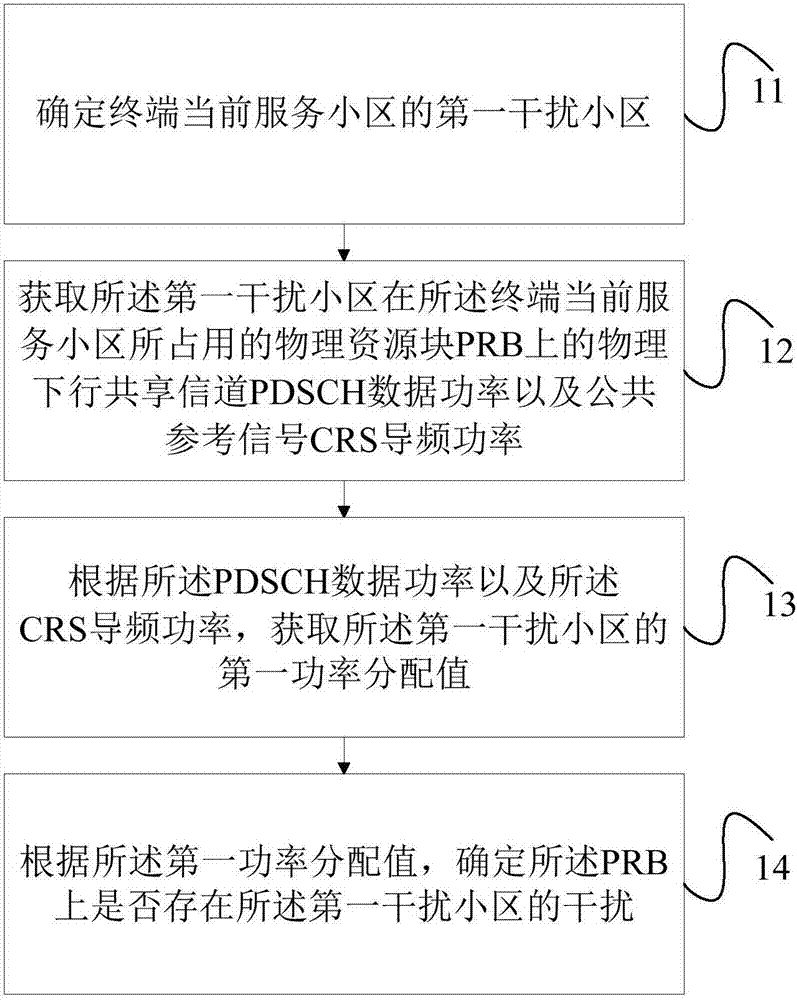
[0127] Such as figure 1 As shown, the interference detection method in Embodiment 1 of the present invention includes:
[0128] Step 11, determining the first interfering cell of the current serving cell of the terminal;
[0129] It should be noted that, in this embodiment, the first interfering cell is the strongest interfering cell of the terminal under the current serving cell. In step 11, the terminal may determine the strongest interfering cell according to its own received signal.
[0130] Step 12, obtaining the physical downlink shared channel PDSCH data power and the common reference signal CRS pilot power of the first interfering cell on the physical resource block PRB occupied by the current serving cell of the terminal;
[0131] In this embodiment, the calculation of the first power allocation value of the strongest interfering cell is mainly performed by using the PDSCH data power and the CRS pilot power, and the first power allocation value in the present inventi...
Embodiment 2
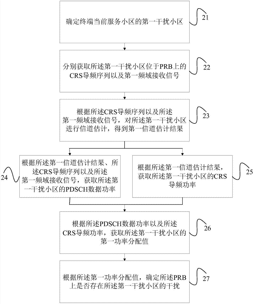
[0138] Such as figure 2 As shown, the interference detection method in Embodiment 2 of the present invention includes:
[0139] Step 21, determining the first interfering cell of the current serving cell of the terminal;
[0140] Wherein, the first interfering cell refers to the strongest interfering cell of the current serving cell.
[0141] Step 22, obtaining respectively the CRS pilot sequence and the first frequency-domain received signal of the first interfering cell located on the PRB;
[0142] The CRS pilot sequence and the first frequency-domain received signal here also refer to the CRS pilot sequence and the first frequency-domain received signal of the strongest interfering cell located on each PRB.
[0143] Step 23, performing channel estimation on the first interfering cell according to the CRS pilot sequence and the first frequency-domain received signal, to obtain a first channel estimation result;
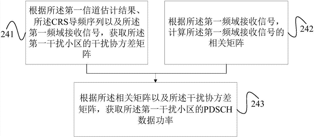
[0144] Step 24: Acquire the PDSCH data power of the first ...
Embodiment 3
[0173] Such as Figure 5 As shown, the interference detection method in Embodiment 3 of the present invention includes:
[0174] Step 51, determining the first interfering cell of the current serving cell of the terminal;
[0175] Wherein, the first interfering cell refers to the strongest interfering cell of the current serving cell.
[0176] Step 52, acquiring the physical downlink shared channel PDSCH data power and common reference signal CRS pilot power of the first interfering cell on the physical resource block PRB occupied by the current serving cell of the terminal;
[0177] Step 53, acquiring a first power allocation value of the first interfering cell according to the PDSCH data power and the CRS pilot power;
[0178] Step 54, divide the data area into intervals according to the power allocation value in the received power allocation set;
[0179] It should be noted that the power allocation set is pre-configured by the base station side and delivered to the term...
PUM
 Abstract
Description
Claims
Application Information
 - R&D
- Intellectual Property
- Life Sciences
- Materials
- Tech Scout
- Unparalleled Data Quality
- Higher Quality Content
- 60% Fewer Hallucinations
Browse by: Latest US Patents, China's latest patents, Technical Efficacy Thesaurus, Application Domain, Technology Topic, Popular Technical Reports.
© 2025 PatSnap. All rights reserved.Legal|Privacy policy|Modern Slavery Act Transparency Statement|Sitemap|About US| Contact US: help@patsnap.com