
Laser beam expander transposition mechanism

A laser beam expander and stepping motor technology, applied in the field of laser beam expander, can solve the problem of low positioning accuracy, achieve the best effect, improve multi-level use, and easy installation and disassembly

Active Publication Date: 2017-09-29
红商培优(山东)企业管理有限公司
View PDF5 Cites 0 Cited by
  • Summary
  • Abstract
  • Description
  • Claims
  • Application Information

AI Technical Summary

Problems solved by technology

[0002] Laser has the advantage of strong collimation, and has been widely used in many industries of national economic construction, but laser is parallel light with divergence angle, which makes the laser spot larger when the laser is emitted to a long distance, and the energy per unit area In order to change the laser spot size of the emitted laser beam at a certain position, it is necessary to change the laser divergence angle, so a laser beam expander is designed in the laser emission path. In order to obtain different laser divergence angles, a laser emission Two laser beam expanders are designed in the optical path, one of which is designed as a structure that can change its position. When a large laser divergence angle is required, the laser beam expander is moved out of the optical path. When a small laser divergence angle is required Move the laser beam expander into the laser optical path, the simple laser beam expander transposition mechanism uses the combination of the circular stopper on the base of the laser beam expander and the positioning pin to determine the position of the beam expander, so that the laser beam expander In the laser emission system, the optical axis of the beam expander coincides with the optical axis of the laser emission system. The advantage of this transposition method is that the structure is simple, but the positioning accuracy of the beam expander is limited by the size accuracy of the circular stopper and the positioning pin. The accuracy is low, and most of the transposition mechanisms can only achieve one specification of beam expander transposition

Method used


Image

  • Laser beam expander transposition mechanism

Examples


Embodiment

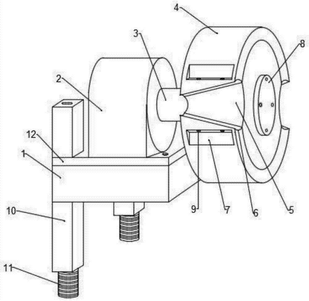
[0015] Such as figure 1 As shown, the present invention provides a technical solution, including a base 1, a cushion plate 12 is installed on the top of the base 1, and rectangular parallelepiped slide rails 10 are longitudinally installed at both ends of the left side of the base 1, so that The inside of the slide rail 10 is screwed with a lead screw 11, the top of the cushion plate 12 is equipped with a stepper motor 2, and the stepper motor 2 is connected with a transposition disc 4 through a coupling 3, and the A splined connection is adopted between the shaft coupling 3 and the transposition disc 4. The main shaft of the coupling 3 traverses the transposition disc 4 and is connected with a shaft disc fixing part 8, and the disc-shaped shaft disc fixing part 8 is fixed on the right side of the transposition disc 4 by screws, and the front and rear sides of the transposition disc 4 are provided with a trapezoidal mirror-expanding assembly groove 5, and the groove walls on b...


PUM


Abstract

The present invention discloses a laser beam expander transposition mechanism. The mechanism comprises a pedestal, the top of the pedestal is provided with a buffer plate, cuboid slide rails are vertically installed at two ends of the left side of the pedestal, leading screws are screwed at the internal portions of the slide rails through screw threads, the top of the buffer plate is provided with a stepping motor, the stepping motor is connected with a transposition plate through a coupling, a splined joint mode is employed between the coupling and the transposition plate, the main shaft of the coupling transversely passes through the transposition plate to connect with a shaft disc fixed part, the disc-shaped shaft disc fixed part is fixed at the right side of the transposition plate through bolts, a trapezoidal beam expander assembling groove is arranged at the front and back sides of the transposition plate, the groove walls of the two sides of the trapezoidal beam expander assembling groove is arc-shaped concave edged, side regulation grooves are arranged at two sides of the trapezoidal beam expander assembling groove, and the side regulation grooves are internally provided with hydraulic expansion screws.

Description

technical field [0001] The invention relates to the technical field of laser beam expanders, in particular to a laser beam expander transposition mechanism. Background technique [0002] Laser has the advantage of strong collimation, and has been widely used in many industries of national economic construction, but laser is parallel light with divergence angle, which makes the laser spot larger when the laser is emitted to a long distance, and the energy per unit area In order to change the laser spot size of the emitted laser beam at a certain position, it is necessary to change the laser divergence angle, so a laser beam expander is designed in the laser emission path. In order to obtain different laser divergence angles, a laser emission Two laser beam expanders are designed in the optical path, one of which is designed as a structure that can change its position. When a large laser divergence angle is required, the laser beam expander is moved out of the optical path. Wh...

Claims


Application Information

Patent Timeline
Patent Type & Authority Applications(China)
IPC IPC(8): G02B27/09
CPCG02B27/0933
Inventor 汪明
Owner 红商培优(山东)企业管理有限公司
Learn More