Monitoring camera fixing equipment

A technology for monitoring cameras and fixed equipment, which is applied in the direction of mechanical equipment, supporting machines, machine tables/supports, etc. It can solve the problems of affecting the normal working stability, cumbersome disassembly process, time-consuming and labor-intensive efficiency, and achieves convenient and repeated installation. Effects of using, improving safety, and preventing electric shock accidents

Active Publication Date: 2017-10-03
上海朋邦实业有限公司
View PDF5 Cites 2 Cited by
  • Summary
  • Abstract
  • Description
  • Claims
  • Application Information

AI Technical Summary

Problems solved by technology

When the existing monitoring camera is installed, the camera is generally directly fixed on the pole by screws and then powered by an external line. When the camera fails and needs to be repaired, it must be disassembled by a screwdriver. It is cumbersome, time-consuming, labor-intensive and inefficient. At the same time, because the external circuit of the camera is exposed to the outside world, it is very prone to short-circuit faults in rainy days, affecting the stability of normal work and causing inconvenience to users.

Method used


Image

  • Monitoring camera fixing equipment
  • Monitoring camera fixing equipment
  • Monitoring camera fixing equipment

Examples


Embodiment Construction

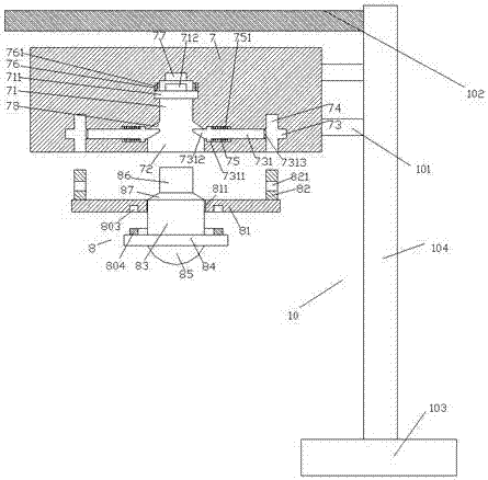
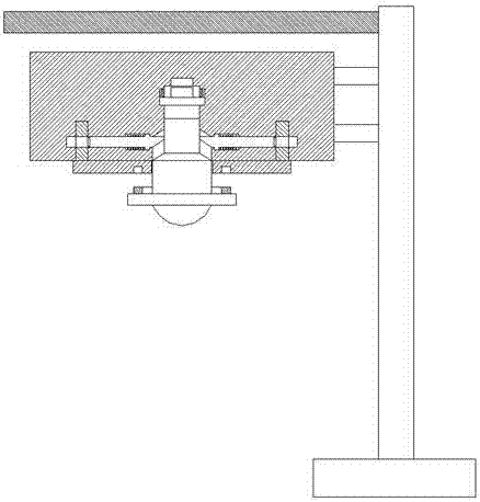
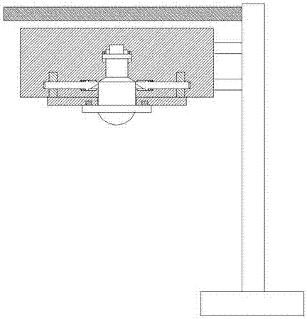
[0023] Such as Figure 1-Figure 5 As shown, a monitoring camera fixing device of the present invention includes a fixing base 7 and a monitoring component 8 used to cooperate with the fixing base 7 and a support component 10 arranged on the right side of the fixing base 7. A first sliding groove 71 is provided at the inner center of the fixed seat 7, and a second sliding groove 72 is provided below the bottom of the first sliding groove 71, and the inner top of the fixed seat 7 above the upper end of the first sliding groove 71 The wall is provided with a power transmission cavity 77, and the inner wall of the fixing seat 7 on both sides of the first sliding groove 71 is provided with a first sliding groove 76, and a pushing block 711 is slidingly fitted in the first sliding groove 76, so that The upper end of the pushing block 711 is provided with a power transmission column 712 corresponding to the power transmission cavity 77, and the upper end of the pushing block 711 in t...


PUM


Abstract

The invention discloses monitoring camera fixing equipment. The monitoring camera fixing equipment comprises a fixing base, a monitoring assembly connected with the fixing base in a matched manner and a supporting assembly arranged on the right side of the fixing base; a first sliding groove is formed in the center position of the interior of the fixing base, a second sliding groove is formed below the bottom end of the first sliding groove, a power transmission cavity is formed in the position, above the upper end of the first sliding groove, at the top wall of the interior of fixing base, first slide grooves are formed in the positions, on the two sides of the above first sliding groove, of the inner side wall of the fixing base, push and pressing blocks are connected to the interiors of the first slide grooves in a sliding and matched manner, and power transmission columns arranged in correspondence to the power transmission cavity are arranged at the upper ends of the push and pressing blocks; and first tension springs are arranged at the upper ends of the push and pressing blocks in the first slide grooves, a clamping groove is arranged between the first sliding groove and the second sliding groove, and locking holes are correspondingly arranged at the positions, on the two sides of the second sliding groove, in the fixing base. The monitoring camera fixing equipment is simple in structure, convenient to disassemble and assemble, stable in running and long in service life, and improves the using safety.

Description

technical field [0001] The invention relates to the technical field of monitoring equipment, in particular to a monitoring camera fixing device. Background technique [0002] With the widespread application of surveillance cameras, the law and order in the city is getting better and better. When the existing monitoring camera is installed, the camera is generally directly fixed on the pole by screws and then powered by an external circuit. When the camera fails and needs to be repaired, it must be disassembled by a screwdriver. It is cumbersome, time-consuming, labor-intensive and inefficient. At the same time, because the external circuit of the camera is exposed to the outside world, it is very prone to short-circuit faults in rainy days, affecting the stability of normal work and causing inconvenience to users. Contents of the invention [0003] The technical problem to be solved by the present invention is to provide a monitoring camera fixing device, which can solve ...

Claims


Application Information

Patent Timeline
IPC IPC(8): F16M13/02F16M11/04
CPCF16M11/04F16M13/02
Inventor 王金超
Owner 上海朋邦实业有限公司
Why Eureka
Try Eureka