Furniture joint

A technology of furniture and recessed parts, which is applied in the direction of furniture connection, furniture parts, household appliances, etc., to achieve the effect of simple operation principle

Active Publication Date: 2017-10-13
IKEA SUPPLY
View PDF14 Cites 1 Cited by
  • Summary
  • Abstract
  • Description
  • Claims
  • Application Information

AI Technical Summary

Problems solved by technology

This would constitute an unacceptable defect

Method used


Image

  • Furniture joint
  • Furniture joint
  • Furniture joint

Examples


Embodiment Construction

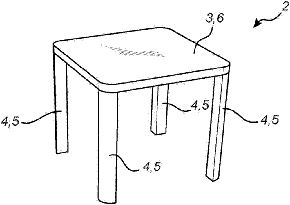
[0028] now go to figure 1 and figure 2, one embodiment of the furniture joint 1 of the present invention is disclosed as being applied to a table 2 comprising a table top 3 and four table legs 4 . It goes without saying that the furniture joint 1 should not be restricted to tables, but is equally applicable to other types of furniture.

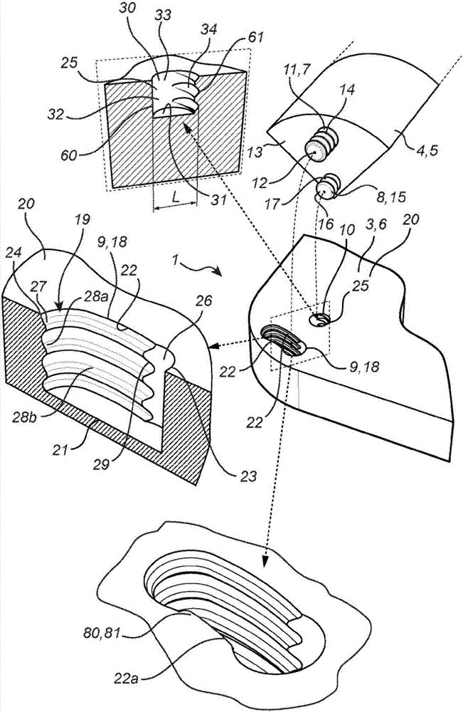
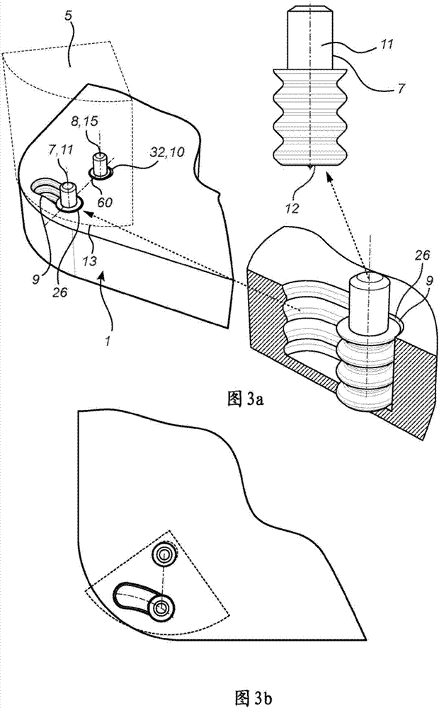
[0029] Each table leg 4 constitutes a first furniture part 5 referred to in this application, while the top 3 constitutes a second furniture part 6 referred to in this application. Each first furniture part 5 comprises a first protruding part 7 and a second protruding part 8 . Furthermore, the second furniture part 6 comprises pairs of first recessed parts 9 and second recessed parts 10 , wherein the number of pairs corresponds to the number of first furniture parts 5 .

[0030] The first protruding portion 7 is formed by a pin 11 extending in the longitudinal direction and having a free end 12 remote from the surface 13 of the first furni...


PUM


Abstract

The invention relates to furniture joint (1) comprising a first furniture part (5) having a first and a second male part (7, 8), and a second furniture part (6) having a first and a second female part (9, 10). The first and the second male parts (7, 8) each are formed by a dowel (11, 15) extending in a longitudinal direction and having a free end (12, 16). The first female part (9) is formed by a recess (18) having a curved extension between a first end portion (23) and a second end portion (24), said first end portion (23) forming an insertion portion (26). The second female part (10) is formed by a recess (25) having a straight-linear extension between a first end portion (60) and a second end portion (61), said first end portion (60) forming an insertion portion (32). The furniture joint (1) is adapted to be set to a mounting position by moving the first furniture part (5) along the longitudinal directions of said dowels (11, 15) such that the insertion portion (26) of the first female part (9) receives the free end (16) of the dowel (11) and such that the insertion portion (32) of the second female part (10) receives the free end (16) of the dowel (15), and from the mounting position to a locking position by rotating the first furniture part (5) in view of the second furniture part (6) such that the dowel (11) forming the first male part (7) is moved along the curved recess (18) from the first end portion (23) to the second end portion (24), while the dowel (15) forming the second male part (8) is rotated and moved along the straight- linear extension of the recess (25) from the first end portion (60) to the second end portion (61). The first and second furniture parts (5, 6) are in said locking position prevented from being separated in the longitudinal direction of said dowels (11, 15).

Description

technical field [0001] The invention relates to a furniture joint between two furniture parts. Background technique [0002] Over the years, a number of different ways have been used to join furniture parts to each other. Different types of mechanical fastening devices are commonly used. It is also known to give furniture parts, eg grooves, different shapes for forming joints between furniture parts. For self-assembling furniture, it is important to be able to assemble different furniture parts to each other in a safe and relatively simple manner. This is especially important when the customer will assemble the furniture themselves. Therefore, there is always a desire to improve joints between different furniture parts. These improvements can relate to the quality of the joints, ie how well the furniture parts fit into each other. These improvements may also relate to manufacturing costs, ease of assembly, and the like. [0003] US2014 / 0205373A1 discloses an example of...

Claims


Application Information

Patent Timeline
Patent Type & Authority Applications(China)
IPC IPC(8): F16B12/44A47B96/06F16B12/12
CPCA47B13/021F16B12/12F16B12/125F16B12/44A47B96/06
Inventor 哈坎·卡尔
Owner IKEA SUPPLY
Why Eureka
Try Eureka