Single-reaction cup luminescence measurement method

A luminescence measurement and reaction cup technology, applied in the field of medical equipment, can solve problems affecting the service life and accuracy of photon counters, and achieve the effects of preventing missing photons, improving collection accuracy, and ensuring service life and accuracy

Active Publication Date: 2017-10-20
SUZHOU HYBIOME BIOMEDICAL ENG CO LTD
View PDF9 Cites 4 Cited by
  • Summary
  • Abstract
  • Description
  • Claims
  • Application Information

AI Technical Summary

Problems solved by technology

In the prior art, the photon collection port of the photon counter is always open. When the top cover of the measurement chamber is opened and placed or the cuvette is removed, external light will enter the photon counter, thereby affecting the service life and accuracy of the photon counter.

Method used


Image

  • Single-reaction cup luminescence measurement method
  • Single-reaction cup luminescence measurement method
  • Single-reaction cup luminescence measurement method

Examples


Embodiment 1

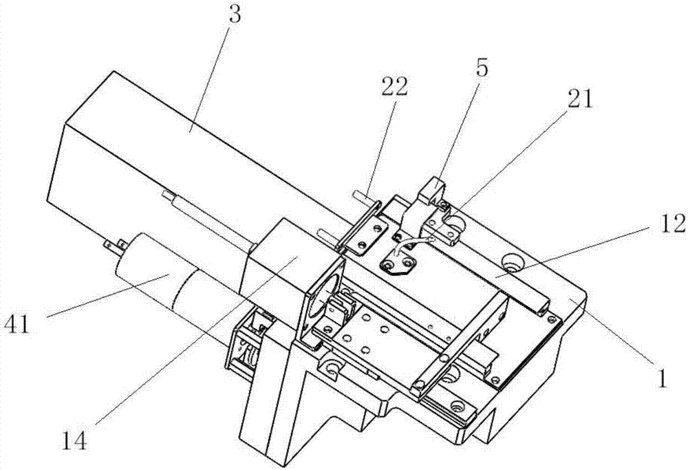
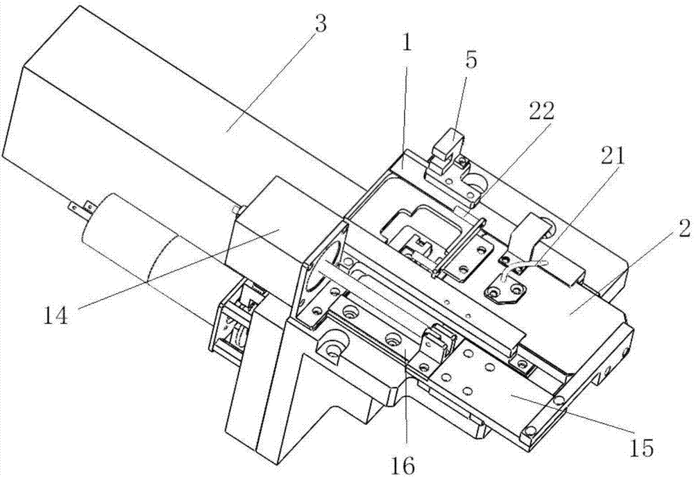
[0033] This embodiment provides a single cuvette luminescence measurement device, such as figure 1 or 2: Include:

[0034] The measurement chamber 1 is open at the top, and has an accommodating cavity for cuvettes inside, and a guide rail 12 on the top, a photon hole on the side, and a switch cover driver 14 installed;

[0035] The top cover 2 is slidably arranged on the guide rail 12 at the top of the measurement chamber 1, and can move along the guide rail 12 under the drive of the switch cover driver 14, so as to be between the position of closing the opening of the measurement chamber 1 and the position of opening the opening of the measurement chamber 1 The top cover 2 is also provided with a reagent adding tube 21. When the top cover 2 is in the position of closing the opening of the measurement chamber 1, the liquid can flow into the cuvette located in the accommodating chamber by injecting the liquid into the reagent adding tube 21, which is convenient for various reac...

Embodiment 2

[0042] This embodiment provides a single cuvette luminescence measurement method, which is carried out in the single cuvette luminescence measurement chamber of Example 1;

[0043] Perform the following steps in order:

[0044] S1: Start the switch cover driver 14 to make the top cover 2 open the opening of the measurement chamber 1, and send the cuvette into the accommodating chamber of the measurement chamber 1;

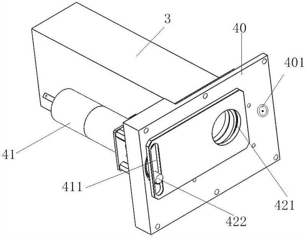
[0045]S2: Start the switch cover driving part 14 to make the top cover 2 close the opening of the measurement chamber 1, and start the rotating driving part 41 to make the through hole 421 on the baffle 42 coincide with the photon passing hole, and start the photon counter 3;

[0046] S3: adding the starter and the triggering agent into the cuvette through the reagent adding tube 21;

[0047] S4: After a period of time, start the rotary drive member 41 to misalign the through hole 421 on the baffle plate 42 with the photon via hole;

[0048] S5: Start the switch ...


PUM


Abstract

The invention relates to a single-reaction cup luminescence measurement method, which includes the following steps: (S1) an opening and closing driver is started, so that the opening of a measurement chamber is opened by a top cover, and a reaction cup is put into a containing cavity of the measurement chamber; (S2) the opening and closing driver is started, so that the opening of the measurement chamber is closed by the top cover, a rotation driver is started, so that a through hole in a baffle is superposed with a photon through hole, and a photon counter is started; (S3) an initiating agent and an excitant are added into the reaction cup via a reagent-adding tube; (S4) after a period of time, the rotation driver is started, so that the through hole in the baffle is staggered from the photon through hole; (S5) the opening and closing driver is started, so that the opening of the measurement chamber is opened by the top cover, and the reaction cup is taken away. Since the photon counter is started and the light passage is opened before the initiating agent and the excitant are added, failure to collect photons is prevented, and the collecting precision is increased.

Description

technical field [0001] The invention relates to a method for measuring luminescence of a single reaction cup, belonging to the technical field of medical devices. Background technique [0002] At present, in vitro diagnosis is the most widely used diagnostic method in the medical field, which refers to collecting body fluids, excreta, and secretions of the human body for chemical composition or chemical reaction analysis, so as to determine human pathological changes. Such as chemiluminescence analysis, molecular diagnosis. These diagnostic methods all use automatic or semi-automatic instruments to add samples, analyze, and give diagnostic reports. This type of instrument has a functional unit—the luminescence value detection unit (that is, the measurement chamber). The measurement chamber is a container structure that can be closed. After the reaction in the measurement chamber emits light, the photon counter measures the number of collected photons, and finally performs q...

Claims


Application Information

Patent Timeline
Patent Type & Authority Applications(China)
IPC IPC(8): G01N21/76
CPCG01N21/76
Inventor 郭金龙沙利烽吴冬苗新利
Owner SUZHOU HYBIOME BIOMEDICAL ENG CO LTD
Why Eureka
Try Eureka