Jitter frequency control circuit and control method

A control circuit and control method technology, applied in the electromagnetic field, can solve the problems of small output capacitance, unbearable output ripple, and inability to use frequency jittering technology, so as to save costs, save pins, reduce production line maintenance costs and The effect of design cost

Active Publication Date: 2017-10-24
MORNSUN GUANGZHOU SCI & TECH +1
View PDF6 Cites 5 Cited by
  • Summary
  • Abstract
  • Description
  • Claims
  • Application Information

AI Technical Summary

Problems solved by technology

[0003] However, frequency shaking technology is not only advantages without disadvantages. In some application environments, such as low-power and small-volume applications, due to the small output capacitor, frequency shaking technology often brings unbearable output ripple; In some communication power supply standards, it is clearly required that frequency shaking technology cannot be used. Therefore, in such applications, chips integrated with frequency shaking technology are often discarded, and ordinary chips are used for PWM control, which limits the use of integrated frequency shaking functions. Chip application range
[0004] On the basis of the existing technology, in order to meet the two application requirements that require frequency shaking and those that do not require frequency shaking, chip designers have to design two types of chips separately, or add additional pins as enabling pins for frequency shaking. Doing so will undoubtedly increase the design and manufacturing costs of chip design manufacturers; and for chip application manufacturers, in order to meet the above two different application requirements, they have to use two types of chips to develop two different solutions to increase the number of applications. The cost of the manufacturer's product design and product management, or separately design the peripheral enable circuit for the extra enable pin, this peripheral enable circuit is often more complicated, which will increase the design difficulty and PCB layout area

Method used


Image

  • Jitter frequency control circuit and control method
  • Jitter frequency control circuit and control method

Examples


Embodiment 1

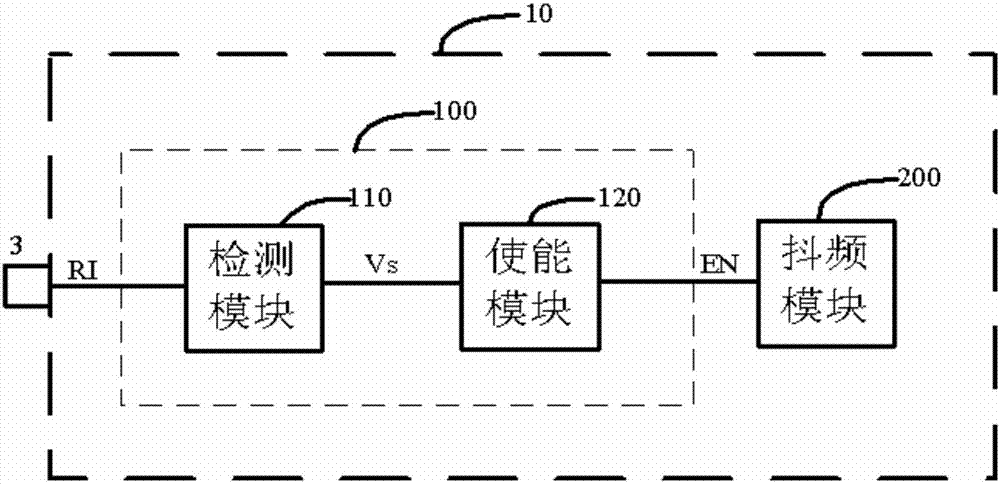
[0023] figure 1 It is a circuit block diagram of a frequency shaking control circuit 100 provided by the present invention. Such as figure 1 As shown, the frequency shaking control circuit 100 includes a detection pin 3, a detection module 110, an enabling module 120 and an EN output terminal connected in sequence. The pin is connected, that is, the frequency setting pin of the detection pin 3 multiplexing switching power supply control chip is RI, and the other end of the detection module 110 is connected with one end of the enabling module 120 to form the node of the RI pin sampling voltage Vs; the enabling module 120 The other end is connected to the frequency shaking module 200 of the chip 10 to form a node for outputting the enable signal EN, that is, the output end of the enable signal EN. The names with the same English code name have the same meaning hereinafter.

[0024] After the chip 10 starts timing 2us, the detection module 110 starts to detect the voltage of t...

Embodiment 2

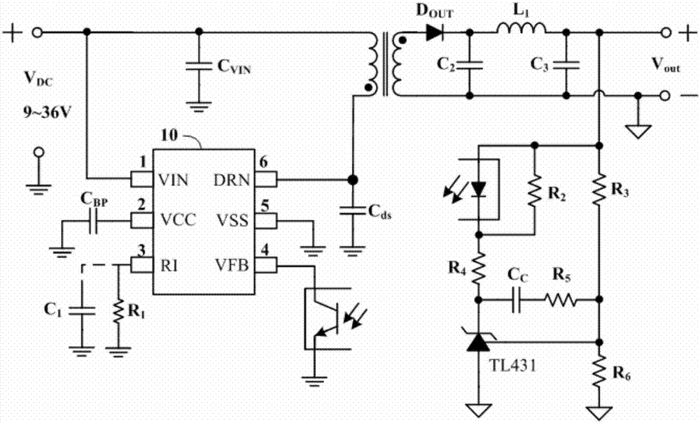
[0029] The circuit block diagram and application circuit structure of the frequency shaking control circuit of the second embodiment are exactly the same as those of the first embodiment. The difference between the two is that the preset condition of Embodiment 2 is that the sampling voltage Vs is greater than the preset voltage V1, that is, in Embodiment 2, if the generated sampling signal Vs is greater than the preset voltage V1, the enable signal EN is issued. , enable the frequency shaking module 200, and add the frequency shaking function to the system.

[0030] Therefore, in Embodiment 2, if the capacitor C1 is not added, the system adds the frequency shaking function; if the capacitor C1 is added, the system does not add the frequency shaking function.


PUM


Abstract

The invention discloses a jitter frequency control circuit which comprises a detection module and an enabling module. The jitter frequency control circuit decides whether to be added with a jitter frequency function by detecting a pin state. Correspondingly, the invention further discloses a jitter frequency control method. The control circuit disclosed by the invention is simple in structure, convenient to use and high in integration; and an application engineer can select whether to adopt the jitter frequency function only by increasing or decreasing one peripheral component (such as a capacitor), so that the design difficulty of the application engineer is reduced, and design steps are simplified.

Description

technical field [0001] The invention relates to the field of electromagnetic technology, in particular to a frequency shaking control circuit and a control method. Background technique [0002] Now, more and more switching power supply manufacturers use frequency shaking technology to reduce electromagnetic interference (EMI). Frequency jittering technology makes the radiated energy distributed in a wide frequency range by properly modulating the switching frequency, and reduces the harmonic amplitude to make it smooth, thereby reducing EMI. [0003] However, frequency shaking technology is not only advantages without disadvantages. In some application environments, such as low-power and small-volume applications, due to the small output capacitor, frequency shaking technology often brings unbearable output ripple; In some communication power supply standards, it is clearly required that frequency shaking technology cannot be used. Therefore, in such applications, chips int...

Claims


Application Information

Patent Timeline
Patent Type & Authority Applications(China)
IPC IPC(8): H02M1/44
CPCH02M1/44
Inventor 唐盛斌符威
Owner MORNSUN GUANGZHOU SCI & TECH
Why Eureka
Try Eureka