
Pavement concrete damping effect test device and method

A technology of shock absorption effect and testing device, applied in soil material testing, material inspection products, etc., can solve the problem of unclear testing device and method, etc.

Active Publication Date: 2017-11-03
HOHAI UNIV
View PDF12 Cites 0 Cited by
  • Summary
  • Abstract
  • Description
  • Claims
  • Application Information

AI Technical Summary

Problems solved by technology

However, the testing devices and methods for the shock-absorbing performance of pavement materials are not clear

Method used


Image

  • Pavement concrete damping effect test device and method
  • Pavement concrete damping effect test device and method
  • Pavement concrete damping effect test device and method

Examples


Embodiment 1

[0043] The following examples are only used to illustrate the technical solutions of the present invention more clearly, but not to limit the protection scope of the present invention.

[0044] 1) Mold modification and test piece preparation

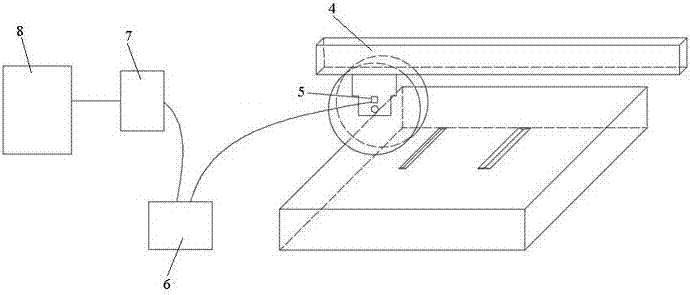
[0045] Select the mold for forming the concrete slab test piece as the object of modification, and weld the three equal parts in the length direction of the mold, such as figure 1 Two steel triangular prisms with different bottom widths are shown, one of which has a rectangular bottom with a length of 100mm and a width of 8mm, and the other has a rectangular bottom with a length of 100mm and a width of 15mm. The heights of the two triangular prisms are both 10mm, and the sides of the triangles are inclined inwardly at 45°, and the center of the bottom surface is 100mm away from the side of the mold, so as to ensure that the edge of the groove will not be damaged when the plate-like specimen is formed by wheel rolling.

[0046] Taking th...


PUM


Abstract

The invention discloses a pavement concrete damping effect test device and method. The test device comprises an acceleration acquisition system and a die for manufacturing a concrete platy test piece containing a notch groove, wherein flanges are formed on the bottom surface of the die; the acceleration acquisition system comprises a rut-depth testing machine; an acceleration sensor is arranged on a steel frame of a wheel of the rut-depth testing machine and connected with a constant-current source adapter; the constant-current source adapter is connected with a data acquisition card; and the data acquisition card is connected with a computer. The damping effect of pavement concrete is quantitatively described according to the ratio of the peak ground acceleration at which the wheel of the testing machine passes through the notch groove of the concrete test piece to a peak ground acceleration generated when the wheel does not pass through the notch groove, and the damping effects of a mixture at different temperatures can be evaluated.

Description

technical field [0001] The invention relates to a device and method for testing the damping effect of concrete pavement, and belongs to the technical field of detection and evaluation of the service performance of concrete pavement. Background technique [0002] Driving comfort requires the evaluation of the damping effect of pavement concrete. With the rapid development of transportation, people have put forward higher requirements for the functions of roads. Not only do roads need to have traditional functions such as smoothness, safety, and durability, but they also expect road surfaces to have sufficient driving comfort. On the one hand, this kind of driving comfort can ensure that when the vehicle is driving fast, there will be no large bumps due to poor road surface roughness, which will affect the ride comfort; on the other hand, it can also slow down the wear of parts and excessive fuel consumption caused by vehicle vibration. . In order to adapt to the improvement...

Claims


Application Information

Patent Timeline
IPC IPC(8): G01N33/24
CPCG01N33/24
Inventor 陈俊殷小晶马谢姚成
Owner HOHAI UNIV
Learn More