Display panel and display device

A technology of display panel and non-display area, which is applied in the fields of instruments, computing, electrical and digital data processing, etc., can solve problems such as difficulty in setting pressure sensors, etc., and achieve the effect of narrowing the frame and enriching application functions.

Active Publication Date: 2017-11-10
SHANGHAI TIANMA MICRO ELECTRONICS CO LTD
View PDF7 Cites 13 Cited by
  • Summary
  • Abstract
  • Description
  • Claims
  • Application Information

AI Technical Summary

Problems solved by technology

However, those skilled in the art have found in the process of implementing the present invention that with the pursuit of narrower borders for display panels, it is difficult to have sufficient space in the non-display area of ​​the array substrate due to the need to arrange circuit components such as display drive circuits. Set up the pressure sensor

Method used


Image

  • Display panel and display device
  • Display panel and display device
  • Display panel and display device

Examples


Embodiment Construction

[0034] The present invention will be further described in detail below in conjunction with the accompanying drawings and embodiments. It should be understood that the specific embodiments described here are only used to explain the present invention, but not to limit the present invention. In addition, it should be noted that, for the convenience of description, only some structures related to the present invention are shown in the drawings but not all structures.

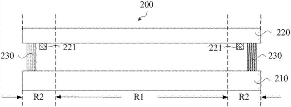
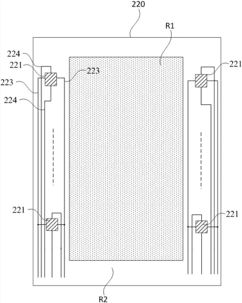
[0035] Figure 1A is a schematic structural diagram of a display panel provided by an embodiment of the present invention, Figure 1B yes Figure 1A A schematic top view of the color filter substrate in the illustrated embodiment. refer to Figure 1A and Figure 1B As shown, the display panel 200 includes an array substrate 210 and a color filter substrate 220 disposed opposite to each other, and the color filter substrate 220 and the array substrate 210 are packaged as a whole by a sealant 230 . The display pan...


PUM


Abstract

Embodiments of the invention provide a display panel and a display device. The display panel comprises a color membrane substrate and an array substrate that are arranged oppositely, wherein the color membrane substrate and the array substrate are packaged into a whole through a sealant. The display panel comprises a display area and a non-display area surrounding the display area. A non-display area of the color membrane substrate is provided with at least two pressure sensors, multiple power signal input lines, and multiple pressure signal output lines, wherein each pressure sensor comprises a signal input end and a signal output end; the multiple power signal input lines are electrically connected with the signal input ends of the pressure sensors respectively; and the multiple pressure signal output lines are electrically connected with the signal output ends of the pressure sensors respectively. According to the display panel provided in the embodiments of the invention, the at least two pressure sensors, the multiple power signal input lines and the multiple pressure signal output lines are arranged in the non-display area of the color membrane substrate, so that the application function of the display panel is increased, and the frame of the display panel is narrowed.

Description

technical field [0001] The present invention relates to the field of display technology, in particular to a display panel and a display device. Background technique [0002] With the development of display technology, display panels with touch functions are applied to various display devices such as mobile terminal devices and information query devices. Thus, the user can touch a corresponding mark on the display panel with a touch object such as a finger, so as to realize the operation of the touch display device. [0003] At present, many display panels have dual functions of collecting touch position information and detecting touch pressure on the basis of touch control, so as to enrich the application range of touch display technology. Usually, the pressure detection function in the display panel is implemented by a pressure sensor. Display panels in the prior art usually include a color filter substrate and an array substrate, and pressure sensors are usually integrat...

Claims


Application Information

Patent Timeline
Patent Type & Authority Applications(China)
IPC IPC(8): G06F3/041
CPCG06F3/0412G06F3/0414G06F3/0416G06F2203/04105G06F3/044G06F3/04164G06F3/04142
Inventor 马少龙卢峰刘亮姚绮君
Owner SHANGHAI TIANMA MICRO ELECTRONICS CO LTD
Why Eureka
Try Eureka