
a 3d printer

A 3D printer and printing device technology, applied in the field of 3D printing, can solve the problems of not meeting the existing needs, affecting normal printing, and unfixed mold trays, etc., and achieve the effect of improving printing efficiency, printing accuracy and simple structure

Active Publication Date: 2019-04-23
南京华塑增材制造有限公司
View PDF4 Cites 0 Cited by
  • Summary
  • Abstract
  • Description
  • Claims
  • Application Information

AI Technical Summary

Problems solved by technology

At present, some 3D printers on the market adopt the technology of "fusion deposition molding". The whole process is to melt the plastic in the printing part, and then form a thin layer by depositing plastic fibers. The problem of easy displacement seriously affects normal printing
In addition, the existing 3D printers cannot stop immediately during the printing process of the printing head rotation, which does not meet the existing needs

Method used


Image

  • a 3d printer
  • a 3d printer
  • a 3d printer

Examples


Embodiment Construction

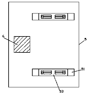
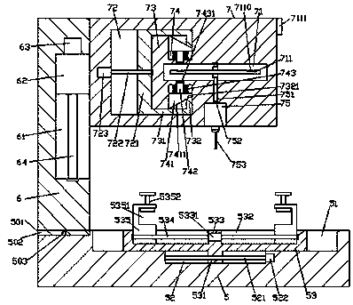
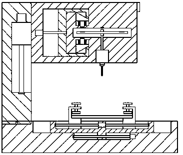
[0023] Such as Figure 1-Figure 5As shown, a 3D printer of the present invention includes a base 5 and a printing device 7 arranged above the top of the base 5, a pillar 6 is arranged on the top left side of the base 5, and a pillar 6 is arranged on the top left side of the base 5. There are first sliding grooves 51 arranged on the same front and back, and a second sliding groove 52 is provided at the middle end of the inner bottom surface of each of the first sliding grooves 51, and the left and right elongating devices are arranged in the second sliding grooves 52. The first screw 521, the first sliding block 53 is slidably connected to the first sliding groove 51, the printing device 7 is provided with a sliding cavity 72, and the right side of the sliding cavity 72 is provided inside There is a convex end 73, which is provided with a locking chamber 71 elongated toward the right side inside the convex end 73, and a printing driving device 75 is fixedly arranged in the bott...


PUM


Abstract

The invention discloses a novel 3D printer comprising a base and a printing device arranged above the top of the base; the top of the left side of the base is provided with a supporting post; first slip grooves are formed in the top of the left side of the base in a back and forth symmetry way; a second slip groove is formed in the middle end of the inner bottom of each of the first slip grooves; the second slip grooves are internally provided with first screw rods extending left and right; the first slip grooves are internally connected with first slip blocks in a slip fit way; the printing device is internally provided with a slip cavity; a convex end is arranged inside the right side of the slip cavity and is internally provided with a locking cavity extending rightwards; a printing driving device is fixedly arranged in the bottom of the printing device; the bottom of the printing driving device is matched and connected with a printing head; a through groove is formed between the top of the printing driving device and the bottom of the locking cavity; and a rotating rod vertically extending is matched with and connected to the inside of the through groove. The novel 3D printer is simple in structure, high in safety and capable of increasing the printing efficiency and improving the printing precision.

Description

technical field [0001] The invention relates to the technical field of 3D printing, in particular to a 3D printer. Background technique [0002] 3D printer, also known as three-dimensional printer, is a machine of rapid prototyping technology. It is based on digital model files, using special wax or plastic and other adhesive materials to manufacture three-dimensional objects by printing layers of adhesive materials. object. 3D printing can directly generate objects of any shape from computer graphics data without machinery or molds, thus greatly shortening the production cycle of products and improving productivity. At present, some 3D printers on the market adopt the technology of "fusion deposition molding". The whole process is to melt the plastic in the printing part, and then form a thin layer by depositing plastic fibers. The problem of easy displacement seriously affects normal printing. In addition, the existing 3D printers cannot realize immediate stop during th...

Claims


Application Information

Patent Timeline
Patent Type & Authority Patents(China)
IPC IPC(8): B29C64/30B33Y30/00
CPCB33Y30/00
Inventor 吴芉
Owner 南京华塑增材制造有限公司
Learn More