Charging pile device for new energy automobile

A technology of new energy vehicles and charging piles, applied in electric vehicle charging technology, charging stations, coupling devices, etc., can solve problems such as being easily touched by metal sheets or metal rods, casualties, and falling off of charging heads, etc. The effect of charging stability, reducing unexpected power failure, and simple structure

Inactive Publication Date: 2017-11-24
深圳永呈实业有限公司
View PDF6 Cites 5 Cited by
  • Summary
  • Abstract
  • Description
  • Claims
  • Application Information

AI Technical Summary

Problems solved by technology

The charging pile is a supporting facility for new energy vehicles, and it is the carrier for charging new energy vehicles. However, the traditional setting mode of the charging pile is single. Accidentally touching the charging head or being affected by pulling the charging cable may cause the charging head to fall off from the charging port, resulting in charging interruption, which seriously affects the normal charging use. At the same time, the conductive sheet in the traditional charging port is generally Set relatively outside, this kind of conductive sheet is easy to be touched by metal sheet or metal rod. Therefore, when people who lack safety awareness insert the metal sheet or rod into the charging socket, electric shock accidents are likely to occur, which may cause personnel accidents. Casualties, great safety hazards

Method used


Image

  • Charging pile device for new energy automobile
  • Charging pile device for new energy automobile
  • Charging pile device for new energy automobile

Examples


Embodiment Construction

[0026] All features disclosed in this specification, or steps in all methods or processes disclosed, may be combined in any manner, except for mutually exclusive features and / or steps.

[0027] Any feature disclosed in this specification (including any appended claims, abstract and drawings), unless expressly stated otherwise, may be replaced by alternative features which are equivalent or serve a similar purpose. That is, unless expressly stated otherwise, each feature is one example only of a series of equivalent or similar features.

[0028] Combine below Figure 1-8 The present invention will be described in detail.

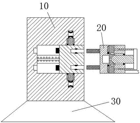
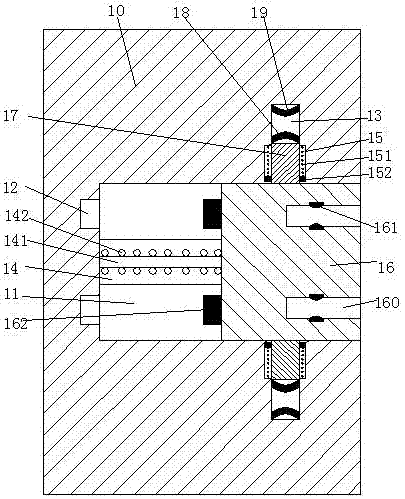
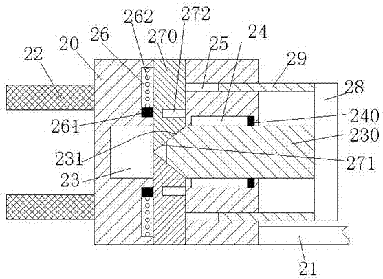
[0029] refer to Figure 1-8 , according to an embodiment of the present invention, a new energy vehicle charging pile device includes a charging pile 10 and a charging terminal 20 connected to the vehicle through a charging cable 21, the charging pile 10 is provided with a sliding cavity 11, the A sliding block 16 is installed slidingly in the sliding cham...


PUM


Abstract

The invention discloses a charging pile device for a new energy automobile. The charging pile device comprises a charging pile and a charging end head connected with the automobile through a charging cable. A sliding cavity is formed in the charging pile; a sliding block is slidably installed in the sliding cavity; charging sockets are arranged in the sliding block in an up-down symmetrical mode; first electric contact pieces are installed in the charging sockets; electricity transmission plug pins are fixedly arranged on the left end face of the sliding block, and plug pin grooves matched with the electricity transmission plug pins are formed in the left end wall of the sliding cavity; extending grooves extending up and down are symmetrically formed in the upper end wall and the lower end wall of the sliding cavity; sliding arms are slidably installed in the extending grooves; second electric contact pieces are fixedly installed on the end faces, far from the sliding cavity, of the sliding arms; third electric contact pieces opposite to the second electric contact pieces are further installed in the extending grooves; and tight-plugging arms matched with the charging sockets are arranged at the left end of the charging end head in an up-down symmetrical mode, an up-down communicating vertical groove is formed in the charging end head, and a horizontal groove penetrating through the vertical groove is further formed in the charging end head, wherein an empty opening of the horizontal groove faces rightwards.

Description

technical field [0001] The invention relates to the field of new energy vehicles, in particular to a charging pile device for new energy vehicles. Background technique [0002] New energy vehicles are gradually replacing traditional vehicles with many advantages such as energy saving, environmental protection and pollution-free, and are widely used. The charging pile is a supporting facility for new energy vehicles, and it is the carrier for charging new energy vehicles. However, the traditional setting mode of the charging pile is single. Accidentally touching the charging head or being affected by pulling the charging cable may cause the charging head to fall off from the charging port, resulting in charging interruption, which seriously affects the normal charging use. At the same time, the conductive sheet in the traditional charging port is generally Set relatively outside, this kind of conductive sheet is easy to be touched by metal sheet or metal rod. Therefore, when...

Claims


Application Information

Patent Timeline
Patent Type & Authority Applications(China)
IPC IPC(8): B60L11/18H01R13/70H01R13/703H01R13/639
CPCB60L53/16B60L53/30B60L53/31H01R13/639H01R13/701H01R13/7036H01R2201/26Y02T10/70Y02T10/7072Y02T90/12Y02T90/14
Inventor 钱明
Owner 深圳永呈实业有限公司
Why Eureka
Try Eureka