An operating rod assembly

A technology for assembling components and operating rods, which is applied in the directions of control components, mechanical control devices, instruments, etc., which can solve the problem that the mold cannot manufacture the clamping structure from two directions, affects the operating comfort, and cannot achieve the sealing effect of covering the rod body of the operating rod. And other issues

Active Publication Date: 2019-03-08
前途汽车(苏州)有限公司
View PDF5 Cites 0 Cited by
  • Summary
  • Abstract
  • Description
  • Claims
  • Application Information

AI Technical Summary

Problems solved by technology

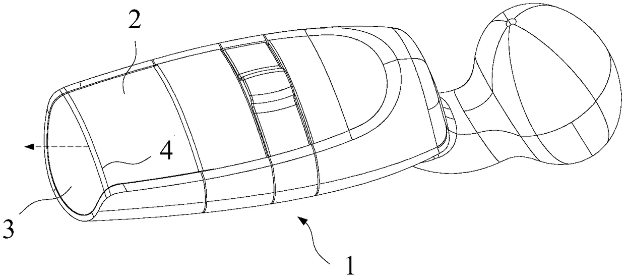
Wherein, the peripheral surface portion and the end surface portion of the decorative part can be locked and connected with the operating rod body 1 through a snap-fit ​​structure, but since the bending part has an angle with the peripheral surface part, if the bending part of the decorative part If the clamping structure is set, it must have an included angle with the ejection direction of the clamping structure on the peripheral surface. Due to the limitation of the ejection direction, the mold cannot manufacture the clamping structure from two directions. Therefore, in the existing situation Next, in this kind of decorative part with a bent part, the bent part is not provided with a snap-fit ​​structure that is locked and connected with the operating rod body
However, due to manufacturing tolerances, stress during use, etc., the decorative part will be subjected to an external force (as shown by the arrow in the figure) from the circumferential surface toward the end surface along the axial direction of the operating rod body, resulting in the bending of the decorative part. Far away from the operating rod body, causing the bending part to warp, unable to achieve the sealing effect covering the operating rod body, and affecting the comfort of operation

Method used


Image

  • An operating rod assembly
  • An operating rod assembly
  • An operating rod assembly

Examples


Embodiment Construction

[0050] In order to have a clearer understanding of the technical features, purposes and effects of the invention, the specific implementation manners of the present invention will now be described with reference to the accompanying drawings, in which the same reference numerals represent the same parts.

[0051] In this article, "schematic" means "serving as an example, example or illustration", and any illustration or implementation described as "schematic" should not be interpreted as a more preferred or more advantageous Technical solutions.

[0052] In order to make the drawings concise, the figures in each figure only schematically show the relevant parts of the present invention, and do not represent the actual structure of the product. In addition, to make the drawings concise and easy to understand, in some drawings, only one of the components having the same structure or function is schematically shown, or only one of them is marked.

[0053] In this article, "upper"...


PUM


Abstract

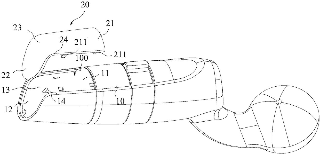
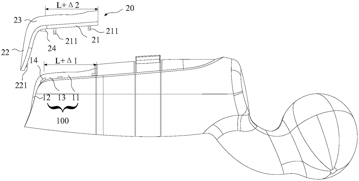
The invention provides an operating rod assembling component. A limiting structure of variable fitting tolerance is formed in the axial direction of a rod body, and position deviation caused by the deviation interval of the dimensional tolerance is compensated in the axial direction of the rod body so that the operating rod assembling component having an integrated and seamless external surface is provided.

Description

technical field [0001] The invention relates to automobile technology, in particular to an operating rod assembly assembly. Background technique [0002] In the joystick used for automobiles, for the sake of aesthetics and the requirement of providing prompt display, it is usually necessary to provide a decorative part covering the body of the joystick on the outer surface of the body of the joystick. [0003] Usually, as figure 1 As shown, the operating rod body 1 has an irregular shape, which is generally a cylinder, and both the circumferential surface 2 and the end surface 3 of the cylinder need to be covered with decorative parts. In order to achieve compliant coverage, most of the decorative parts adopt a separate multi-piece design, that is, a plurality of decorative parts with a planar shape are set on the boundary of the bending part 4 at the junction of the peripheral surface 2 and the end surface 3, and multiple decorative parts are used. The outer surface of th...

Claims


Application Information

Patent Timeline
Patent Type & Authority Patents(China)
IPC IPC(8): G05G1/06
CPCG05G1/06
Inventor 陆群祖军
Owner 前途汽车(苏州)有限公司
Why Eureka
Try Eureka