
Cover plate for electronic ink screen and manufacturing method thereof

A technology of electronic ink screen and manufacturing method, applied in nonlinear optics, instruments, optics and other directions, can solve problems such as position offset, and achieve the effect of eliminating position offset, simplifying printing steps, and simplifying screen design

Pending Publication Date: 2021-11-26
TRANSCEND OPTRONICS (YANGZHOU) CO LTD
View PDF0 Cites 0 Cited by
  • Summary
  • Abstract
  • Description
  • Claims
  • Application Information

AI Technical Summary

Problems solved by technology

[0004] The embodiment of the present application provides a cover plate for an electronic ink screen and its manufacturing method, which solves the problem of positional offset of multiple ink lines near the edge of the visible area in the existing ink printing process

Method used


Image

  • Cover plate for electronic ink screen and manufacturing method thereof
  • Cover plate for electronic ink screen and manufacturing method thereof
  • Cover plate for electronic ink screen and manufacturing method thereof

Examples


Embodiment Construction

[0018] The following will clearly and completely describe the technical solutions in the embodiments of the present application with reference to the drawings in the embodiments of the present application. Obviously, the described embodiments are part of the embodiments of the present application, not all of them. Based on the embodiments in this application, all other embodiments obtained by persons of ordinary skill in the art without creative efforts fall within the protection scope of this application.

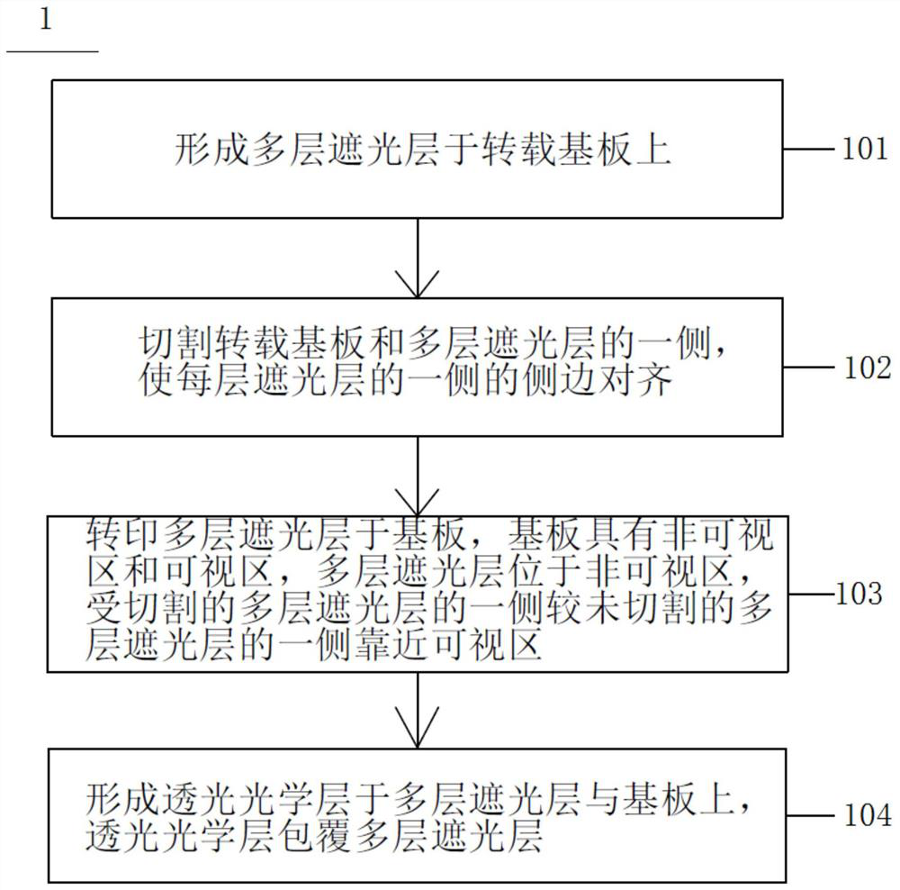
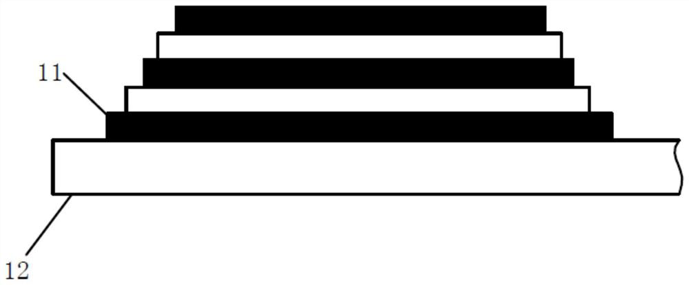
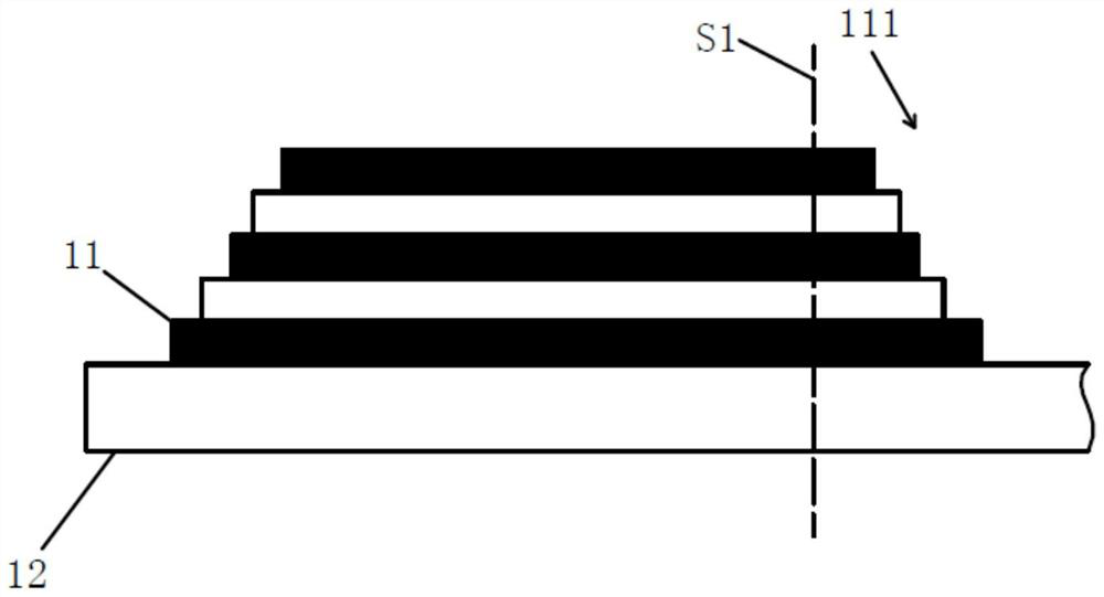
[0019] see figure 1 , which is a schematic flowchart of the steps of the manufacturing method of the cover plate according to an embodiment of the present application. As shown in the figure, the cover plate manufacturing method 1 of this embodiment is mainly used in the manufacturing process of the electronic ink screen, and the cover plate manufacturing method 1 includes steps 101 to 104 . Please also refer to Figure 2 ~ Figure 4 In the cover plate manufacturing metho...


PUM


Abstract

The invention relates to a cover plate for an electronic ink screen and a manufacturing method thereof. The manufacturing method of the cover plate comprises the following steps: forming a plurality of shading layers on a transshipment substrate; cutting one side of the transshipment substrate and one side of the plurality of light shielding layers so that the side edge of one side of each light shielding layer is aligned; transferring a plurality of light shielding layers to the substrate, wherein the substrate is provided with a non-visual area and a visual area, the light shielding layers are located in the non-visual area, and one side of the cut light shielding layers is closer to the visual area than one side of the non-cut light shielding layers; and forming a light-transmitting optical layer on the plurality of light shielding layers and the substrate, wherein the light-transmitting optical layer covers the plurality of light shielding layers. The problem that in an existing ink printing process, the positions of the sides, close to the visible area, of multiple pieces of ink deviate can be solved, and the color of the ink on the printing edge of the visible area is consistent. In addition, the screen design can be simplified, the printing steps are greatly simplified, and the production cost is reduced.

Description

technical field [0001] The present application relates to a method for manufacturing a cover, in particular to a cover for an electronic ink screen and a method for manufacturing the same. Background technique [0002] At present, in order to prevent the backlight of the non-visible area or the light leakage of the front light from affecting the user of the flat electronic ink display panel module with the front light, it usually prints multiple layers of ink in the non-visible area. The existing ink printing process is usually: first print multiple inks on the substrate, then apply optical transparent adhesive on the substrate and multiple inks, and then attach another substrate to the optical transparent adhesive , and finally cut the overall structure and cut out the shape of the cover plate. [0003] In the process of realizing the present application, the applicant found that in the above-mentioned ink printing process, the position of the edge of the side of the multi...

Claims


Application Information

Patent Timeline
Patent Type & Authority Applications(China)
IPC IPC(8): G02F1/167G02F1/1677
CPCG02F1/167G02F1/1677
Inventor 严智清刑芳芳
Owner TRANSCEND OPTRONICS (YANGZHOU) CO LTD
Learn More