Swing press for forging

A stamping machine and forging technology, which is applied in the field of new forging stamping machines, can solve the problem of large stamping load and achieve the effect of eliminating position deviation

Active Publication Date: 2017-04-12
SUMITOMO HEAVY IND LTD
View PDF6 Cites 0 Cited by
  • Summary
  • Abstract
  • Description
  • Claims
  • Application Information

AI Technical Summary

Problems solved by technology

[0010] However, in this prior art, the slider swings but the upper mold itself does not swing, and the upper mold descends to the bottom dead center in a parallel posture with respect to the lower mold and presses down.
[0011] Therefore, it is the same as conventional conventional mechanical presses in that pressure is applied to the entire surface of the die, and the problem of a large press load cannot be solved.

Method used


Image

  • Swing press for forging
  • Swing press for forging
  • Swing press for forging

Examples


Embodiment Construction

[0045] Next, embodiments of the present invention will be described with reference to the drawings.

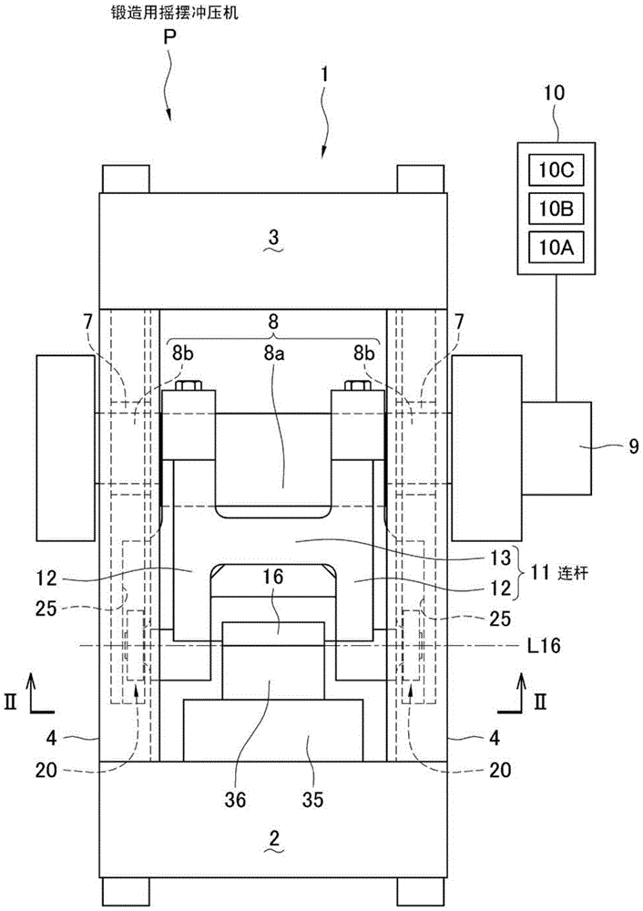
[0046] according to figure 1 and figure 2 , firstly, the basic structure of the forging press machine as the swing press machine P for forging will be described.

[0047] Reference numeral 1 denotes a press machine frame, which includes a lower base 2, an upper top 3, and four columns 4 connecting them.

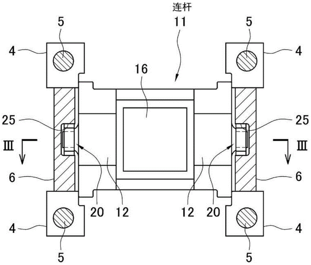
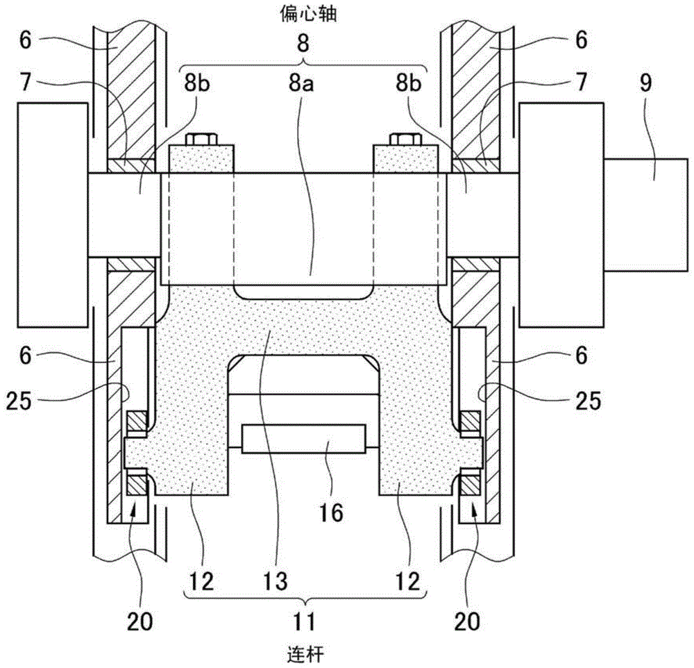
[0048] A tie rod 5 runs through each column 4 , thereby firmly fastening the base 2 and the top 3 . Further, a side frame 6 is fixed between the left front and rear pillars 4, 4, and a side frame 6 is also attached between the right front and rear pillars 4, 4. As shown in FIG.

[0049] Such as figure 1 and image 3 As shown, holes in which bushes 7 are fitted are formed in upper portions of the left and right side frames 6, 6, and eccentric shafts 8 are rotatably inserted into the holes. The illustrated eccentric shaft 8 is a known eccentric shaft composed of an eccen...


PUM


Abstract

PROBLEM TO BE SOLVED: To provide a swing press for forging capable of significantly reducing molding load.SOLUTION: The swing press for forging comprises: an eccentric shaft 8 rotatably attached to a press frame 1; a con-rod 11 which is lifted up and down and is coupled to the eccentric shaft 8; and a bed 2 for mounting a lower die 36 thereon, the press serving as a swing guide for applying swing motion to the lifting motion of the con-rod 11. A lower surface of a top die 16 attached to the lower surface of the con-rod 11 is formed into a curve surface which becomes a salient downward, and the curve surface varies along a direction of the swing motion. Following to rotation of the eccentric shaft 8, the con-rod 11 is lifted up and down and swings by the swing guide, so that the top die 16 attached to the lower surface of the con-rod 11 also swings and the top die 16 gradually contacts and applies pressure to the lower die 36 from one end part to the other end part. The molding is partially performed from the one end part to the other end part of the top die 16, so applied pressure is small, and a drive source of small size may be used.

Description

technical field [0001] The invention relates to a swing punching machine for forging. More specifically, it relates to a new forging press machine of a type that swings a die when pressing or impacting a metal material with upper and lower dies to form an arbitrary shape. Background technique [0002] In a conventional forging mechanical press, as shown in Non-Patent Document 1, an eccentric shaft is rotatably attached to the upper part of the press frame, and the upper end of the connecting rod is attached to the eccentric shaft and the lower end is attached to the toggle pin. To connect with the slider, the rotary motion of the eccentric shaft given by the drive source is converted into the reciprocating motion of the slider. And, in order to satisfy the linearity of the reciprocating motion of the slider, the slider is guided by a guide rail attached to the frame. [0003] An upper mold is installed on the lower surface of the slider converted into reciprocating motion,...

Claims


Application Information

Patent Timeline
Patent Type & Authority Patents(China)
IPC IPC(8): B21J9/06B21J9/18B21J9/20
CPCB21J9/02B21J9/20
Inventor 田渡正史
Owner SUMITOMO HEAVY IND LTD
Why Eureka
Try Eureka