Bridge facility

A technology of facilities and bridges, applied in the direction of electrical components, devices for connecting/disconnecting components, coupling devices, etc., can solve problems such as casualties, potential safety hazards, accidental power failure of electrified maintenance equipment, etc., and achieve high safety effects

Inactive Publication Date: 2017-11-28
重创联合(广州)科技有限公司
View PDF4 Cites 3 Cited by
  • Summary
  • Abstract
  • Description
  • Claims
  • Application Information

AI Technical Summary

Problems solved by technology

In the construction of bridge infrastructure, many plug sockets are preset. These sockets are mainly used for plugging and power supply of electrified maintenance equipment in the later stage. However, the setting mode of these sockets is too simple, and they only rely on friction when plugging in with electrified maintenance equipment. Keeping the state of motion, this kind of power supply state is extremely unstable. When you accidentally kick the plug head or trip the power supply line, it is easy to cause the plug head to fall off and cause the electrified maintenance equipment to accidentally power off; in addition, because the bridge plug seat The setting height is limited, and the internal conductive sheet is set relatively outside. This conductive sheet is easily touched by a metal sheet or a metal rod. Therefore, when a person lacking safety awareness inserts a metal sheet or a metal rod into the socket When the temperature is high, electric shock accidents are prone to occur, causing casualties and posing a greater safety hazard

Method used


Image

  • Bridge facility
  • Bridge facility
  • Bridge facility

Examples


Embodiment Construction

[0021] All features disclosed in this specification, or steps in all methods or processes disclosed, may be combined in any manner, except for mutually exclusive features and / or steps.

[0022] Any feature disclosed in this specification (including any appended claims, abstract and drawings), unless expressly stated otherwise, may be replaced by alternative features which are equivalent or serve a similar purpose. That is, unless expressly stated otherwise, each feature is one example only of a series of equivalent or similar features.

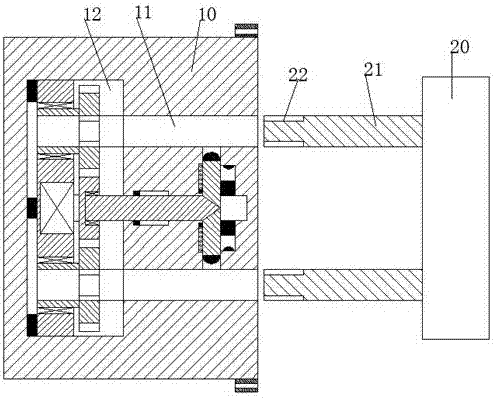
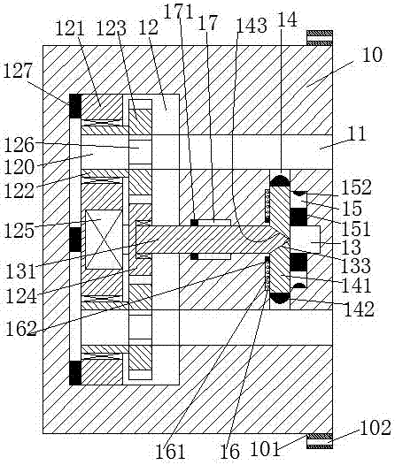
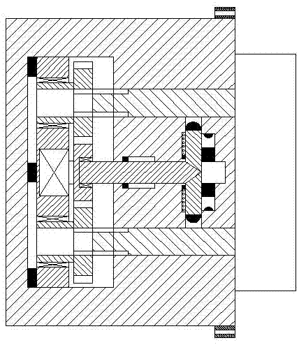
[0023] Such as Figure 1 to Figure 5 As shown, a bridge facility of the device of the present invention includes a plug seat 10 and a plug head 20 connected to electrified maintenance equipment. The left end surface of the plug head 20 is provided with an insertion shaft 21 correspondingly above and below, and the left end of the insertion shaft 21 is provided with a External thread 22; the right side of the upper and lower ends of the bolt s...


PUM


Abstract

The invention provides a bridge facility which comprises a socket and a plug that is connected with electrical maintenance equipment. The right side of the upper end wall and the lower end wall of the socket are correspondingly provided with fixed blocks. The fixed block is internally provided with a fixing hole. The socket is internally provided with insertion troughs which are symmetrically arranged and have openings that face rightward. First sliding troughs which are communicated with each other are arranged between the two insertion troughs. The sliding troughs are internally provided with first sliding board which are correspondingly and smoothly arranged in the vertical direction. One end, which faces the insertion trough, of the first sliding plate, is provided with a second electric conduction plate that is mounted fixedly. One end, which is far from the insertion trough, of the first sliding plate is provided with a first oblique sliding surface. The left end of the insertion trough is further provided with a sliding chamber. A second sliding trough which extends in the left-and-right direction is arranged between the two insertion troughs. The left end of the second sliding trough is communicated with the sliding chamber, and the right end penetrates through the first sliding trough. The right end wall of the first sliding trough is internally provided with placement troughs which are correspondingly arranged in the vertical direction. The sliding chamber is internally provided with a first electric conduction plate which is fixedly connected with the first sliding plate and is connected with the second electric conduction plate through a circuit. The end wall, which is far from the second sliding trough, of the sliding chamber is provided with a power transmission plate which is fixedly mounted and is connected with commercial power.

Description

technical field [0001] The invention relates to the field of bridges, in particular to a bridge facility. Background technique [0002] Bridges are an important infrastructure for urbanization and an important guarantee for alleviating urban traffic congestion. In the construction of bridge infrastructure, many plug sockets are preset. These sockets are mainly used for plugging and power supply of electrified maintenance equipment in the later stage. However, the setting mode of these sockets is too simple, and they only rely on friction when plugging in with electrified maintenance equipment. Keeping the state of motion, this kind of power supply state is extremely unstable. When you accidentally kick the plug head or trip the power supply line, it is easy to cause the plug head to fall off and cause the electrified maintenance equipment to accidentally power off; in addition, because the bridge plug seat The setting height is limited, and the internal conductive sheet is ...

Claims


Application Information

Patent Timeline
IPC IPC(8): H01R13/622H01R13/629H01R13/703
CPCH01R13/7035H01R13/622H01R13/629
Inventor 徐美萍
Owner 重创联合(广州)科技有限公司
Why Eureka
Try Eureka