Damper device

A technology of vibration damping device and natural vibration frequency, applied in transmission device, fluid transmission device, spring/shock absorber, etc., can solve vibration attenuation, increase in weight of torque converter, and large change in rigidity of double-pass shock absorber And other issues

Inactive Publication Date: 2017-11-28
AISIN AW CO LTD
View PDF6 Cites 2 Cited by
  • Summary
  • Abstract
  • Description
  • Claims
  • Application Information

AI Technical Summary

Problems solved by technology

However, if the spring constant of the elastic body is adjusted to rationalize the natural frequency of the vibration paths B and C, the overall rigidity of the two-way damper will vary greatly
In addition, if the weights of the intermediate flange and the turbine combined with the intermediate flange are adjusted to rationalize the two natural frequencies, the weight of the flange, the turbine, and the weight of the entire torque converter will increase.
Therefore, in the above-mentioned two-way damper, it is not easy to properly set the natural vibration frequencies of the vibration paths B and C in order to improve the vibration damping performance. The vibration damping device described in Document 1 cannot attenuate this vibration well

Method used


Image

  • Damper device
  • Damper device
  • Damper device

Examples


Embodiment Construction

[0030] Next, modes for implementing the present invention will be described with reference to the drawings.

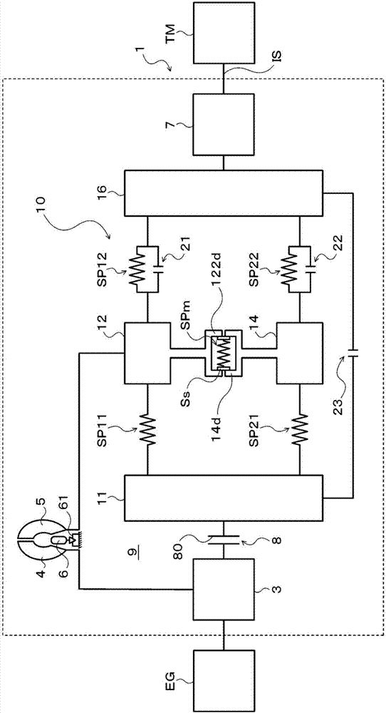
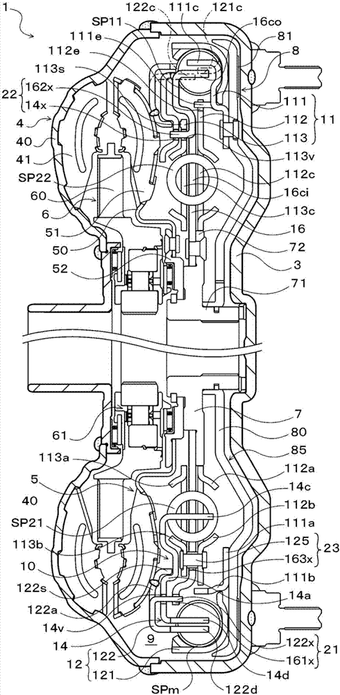
[0031] figure 1 It is a schematic diagram showing the structure of the starting device 1 including the vibration damping device 10 of the present invention, figure 2 It is a sectional view showing the starting device 1 . The starting device 1 shown in the above drawings is mounted on a vehicle having an engine (in this embodiment, an internal combustion engine) EG as a prime mover. The front cover 3, the pump wheel (input side fluid transmission member) 4 fixed to the front cover 3, the turbine wheel (output side fluid transmission member) 5 that can rotate coaxially with the pump wheel 4, and the vibration damping device 10 are connected and fixed on the automatic The damping hub 7 as a power output member on the input shaft IS of a transmission (AT), continuously variable transmission (CVT), dual clutch transmission (DCT), hybrid transmission, or transmission (pow...


PUM


Abstract

The invention provides a damper device. A damper device (10) comprises: a first outer spring (SP11) for transmitting torque between a drive member (11) and a first intermediate member (12); a second outer spring (SP12) for transmitting torque between the first intermediate member (12) and a driven member (16); a first inner spring (SP21) for transmitting torque between the drive member (11) and a second intermediate member (14); a second inner spring (SP22) for transmitting torque between the second intermediate member (14) and the driven member (16); and an intermediate spring (SPm) for transmitting torque between the first intermediate member (12) and the second intermediate member (14). The first and second outer springs (SP11, SP12) corresponding to the first intermediate member (12), which has a smaller natural frequency than the second intermediate member (14), are disposed on the radially outer side of the first and second inner springs (SP21, SP22) corresponding to the second intermediate member (14).

Description

technical field [0001] The invention relates to a vibration damping device having an input member and an output member to which torque from an engine is transmitted. Background technique [0002] Conventionally, a two-way damper used in connection with a torque converter is known as a damper device applicable to a starting device (for example, refer to Patent Document 1). In this damping device, the vibration path from the engine and the lock-up clutch (32) to the output hub (37) is divided into two parallel vibration paths B, C, each of which has a pair of A spring and a separate intermediate flange (36, 38) disposed between the pair of springs. In addition, in order to make the natural vibration frequencies of the two vibration paths different, the turbine wheel (34) of the torque converter is combined with the middle flange (36) of the vibration path B, and the natural vibration frequency of the middle flange (36) of the vibration path B is less than The natural frequen...

Claims


Application Information

Patent Timeline
Patent Type & Authority Applications(China)
IPC IPC(8): F16F15/134F16H45/02
CPCF16F15/134F16F15/12373F16H2045/0231F16H45/02F16D3/12F16F15/12366F16H2045/0294F16F15/13484F16F15/13407
Inventor 泷川由浩长井大树轮嶋雅树坂本贵生伊藤和广铃木展生
Owner AISIN AW CO LTD
Why Eureka
Try Eureka