CT-Detector

A technology for detectors and display components, applied in the fields of computed tomography scanners and electronic components, which can solve problems such as unrecognizable short-term changes in status registers, unnecessary replacement of hardware components, and equipment downtime

Inactive Publication Date: 2017-12-01
SIEMENS HEALTHCARE GMBH
View PDF9 Cites 0 Cited by
  • Summary
  • Abstract
  • Description
  • Claims
  • Application Information

AI Technical Summary

Problems solved by technology

The result may be unnecessary replacement of hardware components and unnecessary equipment downtime
Furthermore, short-term changes of the status register cannot be detected with the current method, since only the register value valid at the read time is always read

Method used


Image

  • CT-Detector

Examples


Embodiment Construction

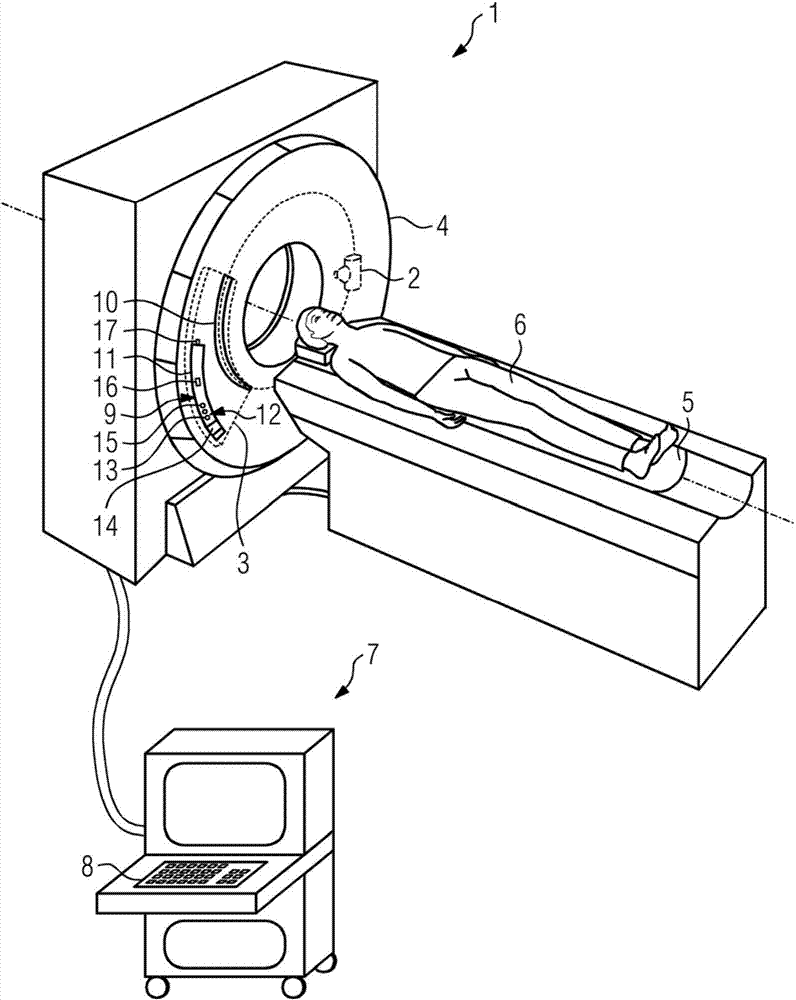
[0021] figure 1 A computed tomography scanner 1 is schematically shown in , which comprises an x-ray source 2 and a CT detector 3 arranged opposite the x-ray source 2 for recording 3D images. The X-ray source 2 and the CT detector 3 are arranged in a gantry 4 . During operation of the computed tomography scanner 1 , the x-ray source 2 and the CT detector 3 rotate about a common axis while recording a plurality of projection images. A 3D image of the object under examination is reconstructed from these projection images.

[0022] Furthermore, the computed tomography scanner 1 also includes a patient table 5 . A patient 6 is brought into the interior of a gantry 4 of a computed tomography scanner 1 by means of a patient couch 5 so that a 3D image of the body region of interest of the patient 6 is generated. For controlling the computed tomography scanner 1 , for example for switching it on and off and for positioning the patient 6 , an operating console 7 with an input field ...


PUM


Abstract

It is a CT detector (3) comprising a housing (9), which is arranged in the housing (9) X-ray detector (10) and having a housing arranged (9) electronic assembly (11) for driving and / or reading of the X-ray detector (10), wherein in the housing (9) is arranged a switched on and off display assembly (12) for visualization of a status information of the CT detector (3).

Description

technical field [0001] The invention relates to a CT detector with a housing, with an X-ray detector arranged in the housing, and with a device for controlling and / or reading the X-ray detector arranged in the housing. electronic components. The invention also relates to a computed tomography scanner with such a CT detector. Background technique [0002] CT detectors of the aforementioned type are, for example, integrated in the gantry of a computed tomography scanner and have a light-tight housing, since the conversion process for measuring x-ray acquisition is photosensitive. Even weak light sources will negatively affect the image quality of a CT detector. Furthermore, at least one electronic component is usually arranged in the housing of the CT detector, which serves to control and / or read out the x-ray detector. In addition, the electronics module can also provide an operating voltage for the x-ray detector. [0003] By electronically controlling the CT detectors, ...

Claims


Application Information

Patent Timeline
Patent Type & Authority Applications(China)
IPC IPC(8): A61B6/03
CPCA61B6/032A61B6/42A61B6/44A61B6/46H05G1/02A61B6/461
Inventor A·格拉夫S·哈特曼T·希尔德沙伊德
Owner SIEMENS HEALTHCARE GMBH
Why Eureka
Try Eureka