Texture mapping device, texture mapping method, and program

A texture mapping and texture technology, applied in image data processing, 3D image processing, instruments, etc., can solve the problems of time-consuming, long processing time, etc.

Inactive Publication Date: 2017-12-01
MITSUBISHI ELECTRIC CORP
View PDF1 Cites 1 Cited by
  • Summary
  • Abstract
  • Description
  • Claims
  • Application Information

AI Technical Summary

Problems solved by technology

However, it is known that the processing of specifying textures generally takes time, and when different textures are mapped to multiple polygons, the processing time becomes longer

Method used


Image

  • Texture mapping device, texture mapping method, and program
  • Texture mapping device, texture mapping method, and program
  • Texture mapping device, texture mapping method, and program

Examples


Embodiment approach 1

[0035] ***Description of structure***

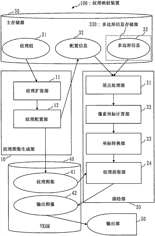
[0036] figure 1 It is a diagram showing the block structure of the texture mapping device 100 according to this embodiment.

[0037] Such as figure 1 As shown, the texture mapping device 100 has a texture atlas generation unit 10 , a rendering unit 20 , a main memory 30 , a VRAM (Video Random Access Memory: Video Random Access Memory) 40 , and an output unit 50 .

[0038] The texture atlas generation unit 10 includes a texture expansion unit 11 and a texture arrangement unit 12 .

[0039] The rendering unit 20 includes a vertex processing unit 21 , a pixel coordinate calculation unit 22 , a coordinate conversion unit 23 , and a texture extraction unit 24 .

[0040] The main memory 30 stores a texture group 31 , arrangement information 32 , and polygon information 33 . A plurality of textures 311 are included in the texture group 31 .

[0041] A texture atlas 41 and an output image 42 are stored in the VRAM 40 .

[0042] In addition...

Embodiment approach 2

[0179] In this embodiment, differences from Embodiment 1 will be mainly described.

[0180] In Embodiment 1, the texture expansion unit 11 needs to expand the texture 311 at least one pixel by one pixel in the XY axis directions. As a result, the size of the texture atlas 41 increases, and the usage of the VRAM 40 increases.

[0181] Therefore, in the present embodiment, the texture pick-up unit 24 does not interpolate the color of the pixel near the position indicated by the conversion coordinate T21 , but uses the color of the pixel closest to the position indicated by the conversion coordinate T21 . By employing such processing, it is not necessary to expand the texture 311, and it is possible to prevent the usage of the VRAM 40 from increasing.

[0182] ***Description of structure***

[0183] Figure 15 It is a diagram showing the block structure of the texture mapping device 100a according to this embodiment. Figure 15 is the same as that described in Embodiment 1 f...

Embodiment approach 3

[0211] In this embodiment, differences from Embodiments 1 and 2 will be described.

[0212] In Embodiment 1, the texture expansion unit 11 needs to expand the texture 311 at least one pixel by one pixel in the XY axis directions. As a result, the size of the texture atlas 41 increases, and the usage of the VRAM 40 increases.


PUM


Abstract

The texture mapping device includes: a texture atlas generating unit (10) that combines a plurality of textures to generate a texture atlas (41), and generates arrangement information (32) of textures for drawing in the texture atlas (41); an information storage unit (330) storing polygon information (33) in which vertex coordinates of polygons in the output image (42) and vertex texture coordinates corresponding to the vertex coordinates in an image drawn on the polygon by the drawing texture are set; a pixel coordinate calculation section (22) that detects the position of a pixel filled with a polygon in the output image (42), and calculates pixel-corresponding texture coordinates corresponding to the position of the pixel in the drawn image; and a coordinate conversion section (23) that The pixel-corresponding texture coordinates are converted into coordinates within the range of the rendering texture on the texture atlas (41).

Description

technical field [0001] The present invention relates to a texture mapping device, a texture mapping method and a program. Background technique [0002] In computer graphics, polygons are mostly used as primitives to describe content. Also, in order to express the surface texture of polygons, a technique of mapping and drawing a two-dimensional image called a texture onto polygons is generally used. [0003] In the case of mapping textures in polygons, in order to reduce the amount of memory to be used, there is a technique of repeating textures with smaller sizes or stretching the ends of textures for mapping. These techniques are called texture loop mode in general GPU (Graphics Processing Unit: Graphics Processing Unit), the mode of repeating mapping is called repeat (repeat), and the mode of stretching and mapping is called clamp (clamp) . [0004] In the case of mapping a texture to a polygon, specify the texture to map and draw the polygon. However, it is known that...

Claims


Application Information

Patent Timeline
Patent Type & Authority Applications(China)
IPC IPC(8): G06T15/04
CPCG06T15/04G06T19/20G06T2219/2012
Inventor 樱井智史下谷光生赤羽哲郎若柳晴彦石黑夏实
Owner MITSUBISHI ELECTRIC CORP
Why Eureka
Try Eureka