Texture mapping apparatus, texture mapping method, and computer readable medium

a technology of texture mapping and texture, applied in the field of texture mapping apparatus, texture mapping method, computer readable medium, etc., can solve the problems of increasing processing time and generally taking time to specify textur

Inactive Publication Date: 2018-02-01
MITSUBISHI ELECTRIC CORP
View PDF3 Cites 1 Cited by
  • Summary
  • Abstract
  • Description
  • Claims
  • Application Information

AI Technical Summary

Benefits of technology

[0013]In a texture mapping apparatus according to the present invention, a polygon information storage unit stores polygon information in which vertex coordinates and vertex texture coordinates are set, the vertex coordinates indicating a location of each vertex of a polygon in an output image, the vertex texture coordinates indicating a location corresponding to the vertex coordinates in an image to be rendered on the polygon. A pixel coordinate calculation unit detects pixel coordinates indicating pixels corresponding to the polygon, and calculates, as pixel-corresponding texture coordinates, coordinates corresponding to the pixel coordinates in the image to be rendered on the polygon. A coordinate conversion unit converts the pixel-corresponding coordinates to coordinates within an area including the texture to be rendered, among the coordinates in the texture atlas, and outputs the coordinates after being converted as converted coordinates. Therefore, the coordinates on the image to be rendered on the polygon by repeating or clamping the texture to be rendered can be converted to the coordinates in the texture atlas. Thus, the texture mapping apparatus provides the effect of being able to perform texture mapping to the polygon by repeating or clamping the texture to be rendered combined into the texture atlas.

Problems solved by technology

However, it is known that the process to specify the texture generally takes time, and the processing time is increased if respectively different textures are mapped to a plurality of polygons.

Method used


Image

  • Texture mapping apparatus, texture mapping method, and computer readable medium
  • Texture mapping apparatus, texture mapping method, and computer readable medium
  • Texture mapping apparatus, texture mapping method, and computer readable medium

Examples


first embodiment

Description of Configuration

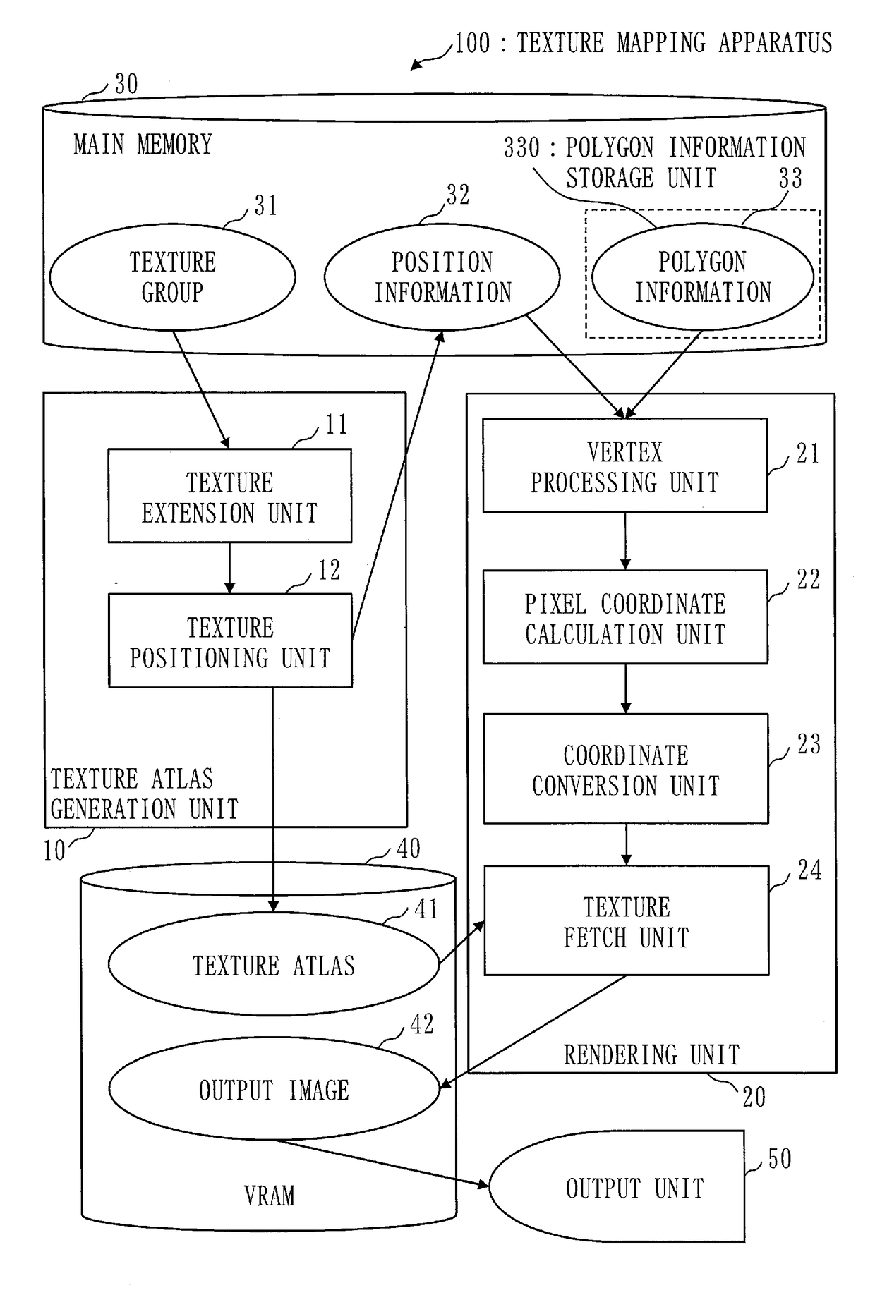
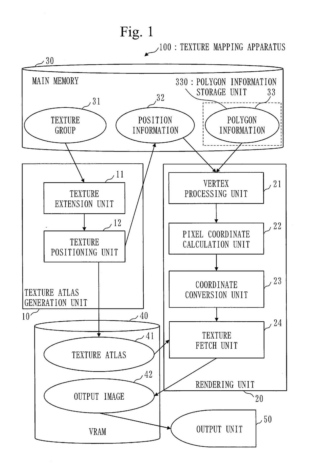
[0033]FIG. 1 is a diagram illustrating a block configuration of a texture mapping apparatus 100 according to this embodiment.

[0034]As illustrated in FIG. 1, the texture mapping apparatus 100 has a texture atlas generation unit 10, a rendering unit 20, a main memory 30, a VRAM (Video Random Access Memory) 40, and an output unit 50.

[0035]The texture atlas generation unit 10 has a texture extension unit 11 and a texture positioning unit 12.

[0036]The rendering unit 20 has a vertex processing unit 21, a pixel coordinate calculation unit 22, a coordinate conversion unit 23, and a texture fetch unit 24.

[0037]The main memory 30 stores a texture group 31, position information 32, and polygon information 33. The texture group 31 includes a plurality of textures 311.

[0038]The VRAM 40 stores a texture atlas 41 and an output image 42.

[0039]Note that a texture is also referred to as a texture image.

[0040]FIG. 5 is a diagram illustrating an example of the textures 311. ...

second embodiment

[0154]In this embodiment, differences from the first embodiment will be mainly described.

[0155]In the first embodiment, the texture extension unit 11 needs to extend the texture 311 at least by one pixel in each of the X-axis and Y-axis directions. As a result, the size of the texture atlas 41 is increased, and the usage of the VRAM 40 is increased.

[0156]In this embodiment, therefore, a texture fetch unit 24 uses the color of a pixel most adjacent to the location indicated by converted coordinates T21, instead of interpolating the colors of pixels around the location indicated by the converted coordinates T21. With this process, it is not necessary to extend textures 311 and an increase in the usage of a VRAM 40 can be prevented.

Description of Configuration

[0157]FIG. 15 is a diagram illustrating a block configuration of a texture mapping apparatus 100a according to this embodiment. FIG. 15 is a diagram corresponding to FIG. 1 described in the first embodiment.

[0158]In this embodimen...

third embodiment

[0178]In this embodiment, differences from the first and second embodiments will be described.

[0179]In the first embodiment, the texture extension unit 11 needs to extend each texture 311 by at least one pixel in each of the X-axis and Y-axis directions. As a result, the size of the texture atlas 41 is increased, and the usage of the VRAM 40 is increased.

[0180]This embodiment describes a texture mapping apparatus wherein the texture wrap mode to be used is only Clamp, and extension of textures is not required and an increase in the memory usage can be prevented.

Description of Configuration

[0181]The configuration of a texture mapping apparatus 100b according to this embodiment is substantially the same as the configuration of FIG. 15 described in the second embodiment.

[0182]In this embodiment, components having substantially the same functions as the components described in the first and second embodiments are given the same reference numerals, and description thereof may be omitted....


PUM


Abstract

Provided are a texture atlas generation unit (10) that generates a texture atlas (41) by combining a plurality of textures, and generates position information (32), in the texture atlas (41), of a texture to be rendered; a polygon information storage unit (330) that stores polygon information (33) in which are set vertex coordinates of the polygon in an output image (42) and vertex texture coordinates corresponding to the vertex coordinates in an image to be rendered on the polygon on the basis of the texture to be rendered; a pixel coordinate calculation unit (22) that detects locations of pixels to be filled in with the polygon in the output image (42), and calculates pixel-corresponding texture coordinates corresponding to locations of pixels in a rendered image; and a coordinate conversion unit (23) that converts the pixel-corresponding texture coordinates to coordinates within an area of the texture to be rendered on the texture atlas (41).

Description

TECHNICAL FIELD[0001]The present invention relates to a texture mapping apparatus, a texture mapping method, and a program.BACKGROUND ART[0002]In computer graphics, a polygon is often used as a primitive for the content to be rendered. In order to express the material of the surface of the polygon, there is a commonly used technique in which the polygon is rendered by mapping a two-dimensional image called a texture to the polygon.[0003]To map the texture to the polygon, there are techniques such as mapping by repeating a small-size texture or mapping by extending the edges of the texture, in order to reduce the amount of memory used. In a commonly used GPU (Graphics Processing Unit), these techniques are called texture wrap modes. The mode in which mapping is performed by repeating is called Repeat, and the mode in which mapping is performed by extending the edges is called Clamp.[0004]When the texture is mapped to the polygon, the polygon is rendered after the texture to be mapped...

Claims


Application Information

Patent Timeline
Patent Type & Authority Applications(United States)
IPC IPC(8): G06T15/04G06T19/20
CPCG06T15/04G06T19/20G06T2219/2012
Inventor SAKURAI, SATOSHISHIMOTANI, MITSUOAKABA, TETSUROWAKAYANAGI, HARUHIKOISHIGURO, NATSUMI
Owner MITSUBISHI ELECTRIC CORP
Why Eureka
Try Eureka