Power supply plugging device

A power supply plug-in and plug-in technology, which is applied to the parts of the connection device, the coupling device, the device for preventing contact with live contacts, etc., can solve the problems of burning electrical equipment, laborious plugging out, unstable power supply connection, etc. , to achieve the effect of reducing the incidence of electric shock accidents, the unlocking operation is simple and convenient, and the locking operation is simple and convenient

Inactive Publication Date: 2017-12-05
王芹芳
View PDF4 Cites 22 Cited by
  • Summary
  • Abstract
  • Description
  • Claims
  • Application Information

AI Technical Summary

Problems solved by technology

[0002] At present, the power-on use of electrical equipment is to directly insert the plug connected to it into the power supply hole of the power supply socket and then power it on. The length of the wires between the plug and the electrical equipment is different, and there is no other locking device to lock the plug after the plug is inserted into the power supply hole. As a result, the sudden power failure of the electrical equipment will result in a reduction in the service life of the electrical equipment, and in serious cases, it will directly cause the burning of the electrical equipment. Therefore, there is a power supply connection between the existing plug and the power supply hole. Instability. In addition, when the electrical equipment is not in use, the plug is often pulled out from the power supply hole, which will cause the power supply hole to be exposed. If there are children in the family who directly insert their fingers or metal rods into the power supply socket In this way, it will cause electric shock accidents, and even cause life-threatening danger to children. There is a great potential safety hazard. Moreover, when the electrical equipment needs to be powered off and the plug is pulled out after use, it is necessary to exert a large force on the plug. It is more laborious to pull out the plug

Method used


Image

  • Power supply plugging device
  • Power supply plugging device
  • Power supply plugging device

Examples


Embodiment Construction

[0017] The preferred embodiments of the present invention will be described in detail below in conjunction with the accompanying drawings, so that the advantages and features of the present invention can be more easily understood by those skilled in the art, so as to define the protection scope of the present invention more clearly.

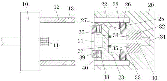
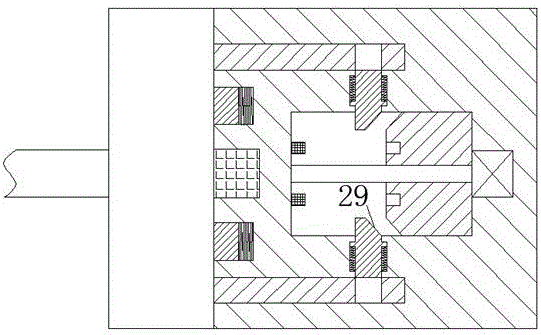
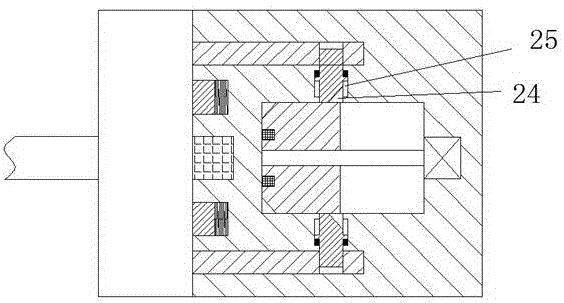
[0018] refer to Figure 1-4 A power supply plug-in device shown includes a plug-in part connected to an electric device through a wire and a power supply part connected to the mains. Two poles 12 are symmetrically arranged at both ends, and a positioning groove 13 is provided at the right end of each of the two poles 12, and a plug 11 is provided in the middle of the right end surface of the hand-held body 10, and the power supply component includes a shell 20. The left end of the casing 20 is provided with a power supply hole 21 with an opening facing left and used to connect with the plug 11 . Inserting column slot 22, the left end surface of ...


PUM


Abstract

The invention discloses a power supply plug-in device, which includes a plug-in part connected to electric equipment through wires and a power supply part connected to the mains. There are two posts symmetrically arranged on the end, a positioning groove is provided at the right end of each of the two posts, a plug is provided in the middle of the right end face of the handle, the power supply component includes a shell, and the left end face of the shell There is a power supply hole opening to the left and used to cooperate with the plug, and the front and rear ends of the left end surface of the housing are symmetrically provided with post slots for cooperating with the post. The structure of the present invention is simple, and the power supply Good stability, avoiding electric shock accidents when plugging and unplugging the plug-in parts, ensuring the safety of people's lives, and the whole device is safe and reliable, the operation of locking and unlocking the post and plug is simple and convenient, and the plug-in parts are pulled out conveniently and labor-saving.

Description

technical field [0001] The invention relates to the field of electric power, in particular to a power supply plug device. Background technique [0002] At present, the power-on use of electrical equipment is to directly insert the plug connected to it into the power supply hole of the power supply socket and then power it on. The length of the wires between the plug and the electrical equipment is different, and there is no other locking device to lock the plug after the plug is inserted into the power supply hole. As a result, the electrical equipment is suddenly cut off, so that the service life of the electrical equipment is reduced, and if it is serious, it will directly cause the electrical equipment to be burned. Therefore, there is a power supply connection between the existing plug and the power supply hole. Instability. In addition, when the electrical equipment is not in use, the plug is often pulled out from the power supply hole, which will cause the power suppl...

Claims


Application Information

Patent Timeline
Patent Type & Authority Applications(China)
IPC IPC(8): H01R13/627H01R13/629H01R13/703H01R13/44
CPCH01R13/6275H01R13/44H01R13/629H01R13/7035
Inventor 王芹芳
Owner 王芹芳
Why Eureka
Try Eureka