Supercharge Your Innovation With Domain-Expert AI Agents!

Cup

A technology for water cups and cups, which is applied to water boiling appliances, heating devices, electrical components, etc. It can solve the problems of reduced service life of cups, easy electric shock accidents, unstable power supply connections, etc., and achieves low production costs. The effect of avoiding electric shock accidents and ensuring safe and stable power supply

Inactive Publication Date: 2017-12-08
戚天儿
View PDF3 Cites 0 Cited by
  • Summary
  • Abstract
  • Description
  • Claims
  • Application Information

AI Technical Summary

Problems solved by technology

[0002] The water cup is a commonly used utensil in people's daily life. With the continuous advancement of science and technology, the function of the water cup is not completely limited to the function of storing water, but also has the function of boiling water. When boiling water, the power transmission terminal needs to be inserted into the power transmission The power transmission terminal of the cup body can be directly inserted into the power supply hole of the power transmission frame to cooperate with the power supply. Although this plugging method is very convenient to operate, the length of the wire between the power transmission terminal and the cup body is different. , when in use, the wires are often placed randomly. If someone accidentally kicks and hits the wires by mistake, this will cause the power transmission terminal to be directly disconnected from the matching connection with the power supply hole of the power transmission frame, resulting in a sudden power failure of the cup. As a result, the service life of the cup is reduced, and if it is serious, it will directly cause the cup to be burned. Therefore, there is a potential safety hazard of unstable power supply connection in the existing power transmission terminal and power supply slot, and the existing power transmission Terminals are prone to electric shock accidents during plugging and unplugging

Method used


Image

  • Cup
  • Cup
  • Cup

Examples


Embodiment Construction

[0020] The preferred embodiments of the present invention will be described in detail below in conjunction with the accompanying drawings, so that the advantages and features of the present invention can be more easily understood by those skilled in the art, and the protection scope of the present invention will be defined more clearly.

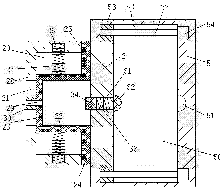
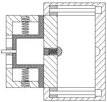
[0021] Refer to Figure 1-6 The water cup shown includes a power transmission frame 5 and a power transmission terminal 1 connected to a cup body 10 through a wire 11. The cup body 10 is provided with an arm 12 on the left end surface and a water outlet 13 on the right end surface. The power transmission frame 5 is provided with a sliding cavity 50 with a left port, the sliding cavity 50 can be smoothly provided with the sliding plate 2 left and right, the center of the right end wall of the sliding cavity 50 is provided with a power transmission groove 51, the front and rear ends of the sliding cavity 50 Correspondingly, a first sliding cavity ...


PUM


Abstract

The invention discloses a cup including a power transmission frame and a power transmission terminal which is connected with a cup body through a wire. The cup body is equipped with a handle on the left end face and a water outlet on the right end face. The power transmission frame is internally provided with a sliding cavity opened leftward. A sliding plate is arranged in the sliding cavity in such a way that the sliding plate can smoothly slide from side to side. A power transmission slot is arranged in the center of the right end wall of the sliding cavity. First sliding cavities are correspondingly arranged in the front and rear end walls of the sliding cavity. Convex arms connected with the first sliding cavities in a sliding fit manner are correspondingly arranged on the right sides of the front and rear end faces of the sliding plate. A smooth sliding piece used for pushing the corresponding convex arm to smoothly slide from side to side is arranged in each first sliding cavity. The cup has the advantages of simple overall structure, low production cost, and safe and stable power supply. The occurrence of electric shock in life is reduced, and power failure of the cup body caused by mistaken kick or collision is avoided. Moreover, the locking of the power transmission terminal is safe and reliable, and the whole device is simple and convenient to operate.

Description

Technical field [0001] The invention relates to the field of water cups, in particular to a water cup. Background technique [0002] The water cup is a commonly used appliance in people’s daily life. With the continuous advancement of technology, the function of the water cup is not completely limited to the function of storing water, but also has the function of boiling water. When boiling water, the power transmission terminal needs to be inserted into the power transmission It can only be used after power is on in the rack. The power transmission terminal of the cup body can be directly inserted into the power supply hole of the power transmission rack for connection to be energized. Although this plug-in method is very convenient to operate, the length of the wire between the power transmission terminal and the cup body is different. When in use, the wires are often placed randomly. If someone accidentally kicks and hits the wires by mistake, the power transmission terminal w...

Claims


Application Information

Patent Timeline
IPC IPC(8): H01R13/639H01R13/70A47J27/21A47J36/24
CPCH01R13/639A47J27/21008A47J36/2483H01R13/701
Inventor 戚天儿
Owner 戚天儿
Features
  • R&D
  • Intellectual Property
  • Life Sciences
  • Materials
  • Tech Scout
  • Unparalleled Data Quality
  • Higher Quality Content
  • 60% Fewer Hallucinations
Learn More