A kind of dust collector equipment

A technology for dust collectors and equipment, which is applied in chemical instruments and methods, separation methods, and separation of dispersed particles, etc., which can solve problems such as applying large forces, unstable power supply connections, and detachment of bumping blocks to increase safety. , Simple and convenient locking operation, simple and convenient locking and unlocking operation

Active Publication Date: 2018-10-16
YIWU FENGQING TECH CO LTD
View PDF7 Cites 0 Cited by
  • Summary
  • Abstract
  • Description
  • Claims
  • Application Information

AI Technical Summary

Problems solved by technology

[0002] At present, the electrification of the dust collector is mainly to insert the bumper block connected to the dust collector into the power transmission port of the power transmission terminal body and clamp it to energize. Although this clamping method is simple to operate, after the bumper block is inserted into the power transmission port The bumper block can still be pulled out directly. When the kicker hits the cable connected between the bumper block and the dust collector by mistake, the bumper block will be separated from the power transmission port and locked, resulting in a sudden power failure of the dust collector. Therefore, the existing clamping method has the risk of unstable power supply connection, which may easily cause the dust collector to be damaged due to a sudden power failure, and the existing clamping method requires a large force to be applied when the bumper is pulled out. , it is more laborious to pull out

Method used


Image

  • A kind of dust collector equipment
  • A kind of dust collector equipment
  • A kind of dust collector equipment

Examples


Embodiment Construction

[0019] The preferred embodiments of the present invention will be described in detail below in conjunction with the accompanying drawings, so that the advantages and features of the present invention can be more easily understood by those skilled in the art, so as to define the protection scope of the present invention more clearly.

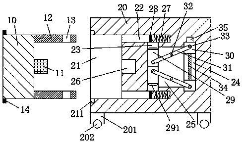
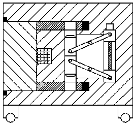
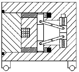
[0020] refer to Figure 1-4 The shown dust collector equipment includes a power transmission head and a power transmission end body connected to the dust collector. The power transmission head includes a hand pinch block 10, and the front and rear ends of the right end surface of the hand pinch block 10 are opposite to each other. Two latches 12 are provided, and a lock groove 13 is provided at the right end of each of the two latches 12, and a touch block 11 is provided at the center of the right end surface of the hand pinch block 10, and the power transmitting end body includes a casing 20 , the bottom end surface of the housing 20 is fixedly ...


PUM


Abstract

The invention discloses novel dust remover equipment. The novel dust remover equipment comprises a power transmission head connected with a dust remover and a power transmission terminal body, wherein the power transmission head comprises a pinching block; two bolts are oppositely arranged at the front end and the rear end of the right end surface of the pinching block; a lock slot is formed in the right end of each bolt; a touch block is arranged in the center of the right end surface of the pinching block; the power transmission terminal body comprises a housing; legs are fixedly mounted at the periphery of the bottom end surface of the housing; rollers are mounted at the bottoms of the legs in a rolling manner; and a clamping groove, of which the opening faces the left, used for being connected with the pinching block in a matched manner is formed in the left end surface of the housing. The novel dust remover equipment is simple in structure and good in power supply stability, the electrified use safety of the dust remover is improved, the whole novel dust remover equipment is safe and reliable in running; locking and unlocking of the bolts and the touch block are simple and convenient; and the power transmission head can be conveniently pulled out with less effort.

Description

technical field [0001] The invention relates to the field of dust collectors, in particular to dust collector equipment. Background technique [0002] At present, the electrification of the dust collector is mainly to insert the bumper block connected to the dust collector into the power transmission port of the power transmission terminal body and clamp it to energize. Although this clamping method is simple to operate, after the bumper block is inserted into the power transmission port The bumper block can still be pulled out directly. When the kicker hits the cable connected between the bumper block and the dust collector by mistake, the bumper block will be separated from the power transmission port and locked, resulting in a sudden power failure of the dust collector. Therefore, the existing clamping method has the risk of unstable power supply connection, which may easily cause the dust collector to be damaged due to a sudden power failure, and the existing clamping me...

Claims


Application Information

Patent Timeline
Patent Type & Authority Patents(China)
IPC IPC(8): B01D46/00
CPCB01D46/0084B01D46/4245
Inventor 方新刚
Owner YIWU FENGQING TECH CO LTD
Why Eureka
Try Eureka