Practical dust removing device

A dust collector and equipment technology, which is applied to the parts of the connection device, the device to prevent contact with live contacts, and electrical components, etc., can solve the problems of power failure of the dust collector, exposed power transmission port, unstable power supply connection, etc., and achieve Safe and stable power supply, simple and convenient operation, and good power supply stability

Inactive Publication Date: 2017-12-22
戎佰腾
View PDF0 Cites 1 Cited by
  • Summary
  • Abstract
  • Description
  • Claims
  • Application Information

AI Technical Summary

Problems solved by technology

[0002] At present, the electrification of the dust collector is to directly insert the power transmission part connected to it into the power transmission port of the power transmission base to connect the power supply, and the connection between the power transmission base and the power supply will always be in the power state. The length of the cable between the power transmission part and the dust collector is different, and there is no other locking device to lock the power transmission part after the power transmission part is inserted into the power transmission port. When the cable is kicked, it will cause the power transmission part from The detachment of the power transmission port will lead to a sudden power failure of the dust collector, and even directly cause the burning of the dust collector. Therefore, the existing cooperation method between the power transmission part and the power transmission port has a potential safety hazard of unstable power supply connection. In addition, when the dust collector is not in use, the power transmission part is often pulled out from the power transmission port, which will cause the power transmission port to be exposed, and there is a great potential safety hazard

Method used


Image

  • Practical dust removing device
  • Practical dust removing device
  • Practical dust removing device

Examples


Embodiment Construction

[0018] The preferred embodiments of the present invention will be described in detail below in conjunction with the accompanying drawings, so that the advantages and features of the present invention can be more easily understood by those skilled in the art, so as to define the protection scope of the present invention more clearly.

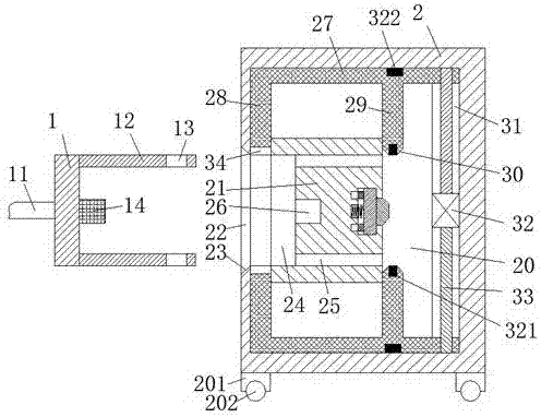
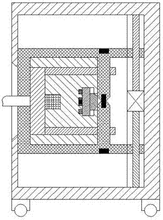
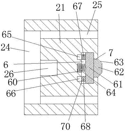
[0019] refer to Figure 1-4 The shown practical dust collector equipment includes a power transmission part and a power transmission seat connected to the dust collector through a cable 11. The power transmission part includes a push rod 1, and the front and rear ends of the right end surface of the push rod 1 are opposite to each other. There are two bolts 12, and the right ends of the two bolts 12 are provided with a slot 13, and the center of the right end of the push rod 1 is provided with a contact arm 14, and the power transmission seat includes a base 2, and the base The bottom of the base 2 is fixedly equipped with a foot column 201 aroun...


PUM


Abstract

The invention discloses a practical dust remover equipment, which comprises a power transmission part connected to the dust collector through a cable and a power transmission seat. Two bolts, the right ends of the two bolts are provided with over grooves, the center of the right end surface of the push rod is provided with a contact arm, the power transmission seat includes a base, and a hollow groove is arranged in the base. The center of the left end face of the base is provided with an entrance connected to the hollow groove. The whole device can complete the power-off and power-on of the contact arm through the operation of a driving machine, that is, the power-off and power-on of the dust collector. The operation is simple and convenient, and the power supply Good stability, safe and reliable operation, and the cooperation between the contact arm and the power transmission port is simple and convenient.

Description

technical field [0001] The invention relates to the field of electric power, in particular to a practical dust collector equipment. Background technique [0002] At present, the electrification of the dust collector is to directly insert the power transmission part connected to it into the power transmission port of the power transmission base to connect the power supply, and the connection between the power transmission base and the power supply will always be in the power state. The length of the cable between the power transmission part and the dust collector is different, and there is no other locking device to lock the power transmission part after the power transmission part is inserted into the power transmission port. When the cable is kicked, it will cause the power transmission part from The detachment of the power transmission port will lead to a sudden power failure of the dust collector, and even directly cause the burning of the dust collector. Therefore, the e...

Claims


Application Information

Patent Timeline
Patent Type & Authority Applications(China)
IPC IPC(8): H01R13/639H01R13/44
CPCH01R13/639H01R13/44
Inventor 戎佰腾
Owner 戎佰腾
Why Eureka
Try Eureka