A constant displacement control method and device for a friction stir welding spindle
A friction stir and displacement control technology, applied in welding equipment, manufacturing tools, non-electric welding equipment, etc., can solve the problem that the joint is difficult to guarantee according to the quality, and achieve the effect of avoiding weak bonding defects, high quality consistency, and ensuring welding quality.
- Summary
- Abstract
- Description
- Claims
- Application Information
AI Technical Summary
Problems solved by technology
Method used
Image
Examples
Embodiment 1
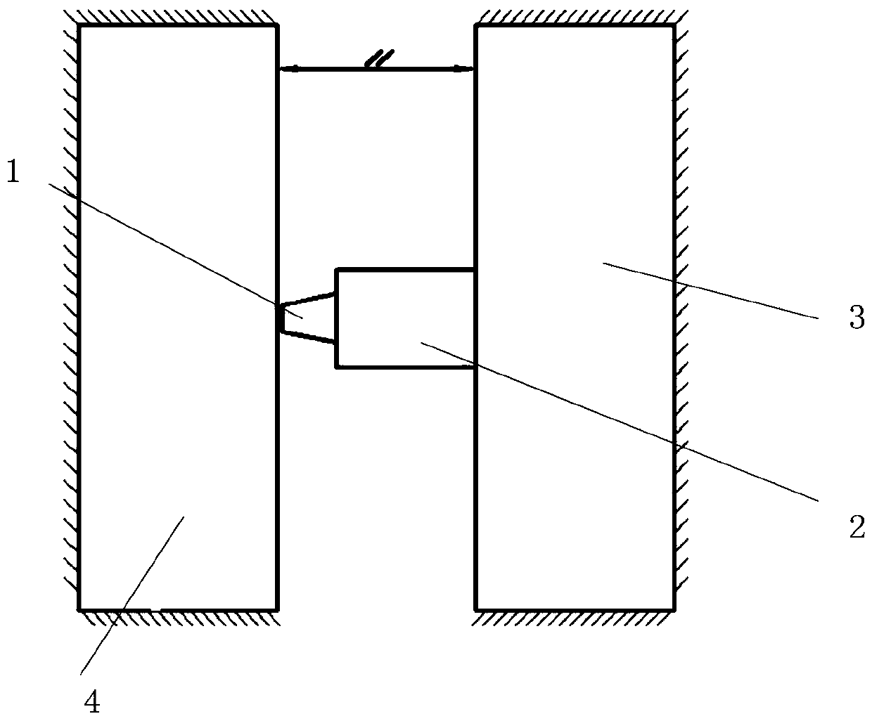
[0121] This embodiment provides a vertical longitudinal seam friction stir welding equipment, such as Figure 4 As shown, the main body of the welding main frame mechanism 3 has strong rigidity and no deformation occurs during welding, while the rigidity of the welding back support plate 4 is weak, and outward deflection occurs under the axial upsetting force of the welding main shaft 2 The deformation will cause the distance between the end of the stirring head and the support mechanism 4 of the welding back to change during the welding process. When the welding spindle 2 is close to the upper and lower ends, the amount of deflection is small, and when it is close to the middle of the support mechanism, the deflection The largest amount of curvature;
[0122] a. In the no-load state, the running frame mechanism 3 of the main engine, the welding back support mechanism 4 and the follow-up measuring device 5 are parallel to each other, and the follow-up measuring device 5 and th...
Embodiment 2
[0126] This embodiment provides a horizontal longitudinal seam friction stir welding equipment, such as Figure 5 As shown, the welding main machine running frame mechanism 3 has weak rigidity and is prone to deformation during welding, while the back supporting mechanism 4 has strong rigidity and does not deform during welding.
[0127] a. Place the follow-up measuring device 5 on one side of the main engine running frame mechanism 3, the main engine running frame mechanism 3, the welding back support mechanism 4 and the follow-up measuring device 5 are parallel under no-load state, but follow-up under loading state The dynamic measuring device 5 is also parallel to the welding back supporting mechanism 4;
[0128] b. When welding starts, that is, in the loading state, the follow-up measuring device 5 and the welding main shaft 2 move synchronously, in the same direction, and at a constant speed in the vertical direction; Measure the deformation δ1, and feed back the signal ...
Embodiment 3
[0131] This embodiment provides a kind of friction stir welding equipment, such as Figure 6 As shown, the rigidity of the main engine running frame mechanism 3 and the welding back support mechanism 4 are relatively weak, and deformation will occur during the welding process.
[0132] a. Set the first follow-up measuring device 5a outside the main machine running frame mechanism 3, and set the second follow-up measuring device 5b outside the welding back supporting mechanism 4. The main machine running frame mechanism 3, the welding back support mechanism 4, the first follow-up measuring device 5a and the second follow-up measuring device 5b are in a parallel state under no-load state, and the first follow-up measuring device 5a and the second follow-up measuring device 5b are in a loaded state. The second follow-up measuring device 5b is in a parallel state;
[0133] b. When welding starts, that is, under the loading state, the first follow-up measuring device 5a, the secon...
PUM
 Abstract
Description
Claims
Application Information
 - R&D
- Intellectual Property
- Life Sciences
- Materials
- Tech Scout
- Unparalleled Data Quality
- Higher Quality Content
- 60% Fewer Hallucinations
Browse by: Latest US Patents, China's latest patents, Technical Efficacy Thesaurus, Application Domain, Technology Topic, Popular Technical Reports.
© 2025 PatSnap. All rights reserved.Legal|Privacy policy|Modern Slavery Act Transparency Statement|Sitemap|About US| Contact US: help@patsnap.com


