Testing and loading device for pure shear on shear type link beam

A technology of loading device and energy-dissipating beam, which is applied in the direction of applying stable shear force to test the strength of materials, measuring devices, instruments, etc. Problems such as pure shear force performance and uneconomical performance of shear-type energy-dissipating beams

Active Publication Date: 2017-12-15
LANZHOU UNIVERSITY OF TECHNOLOGY
View PDF4 Cites 3 Cited by
  • Summary
  • Abstract
  • Description
  • Claims
  • Application Information

AI Technical Summary

Problems solved by technology

[0002] In the existing loading test devices for shear-type energy-dissipating beam sections, the shear-type energy-dissipating beam section is loaded as a part of the frame beam. The disadvantages are: (1) Since it is not loaded independently, this The method cannot obtain the mechanical performance of the real shear-type energy-dissipating beam section; (2) After the shear-type energy-dissipating beam section is damaged, the entire frame beam and the shear-type energy-dissipating beam section need to be replaced when retesting , time-consuming and uneconomical; (3) It is impossible to realize the stress state of the shear-type energy-dissipating beam segment in pure shear, and it is impossible to accurately obtain the mechanical performance of the shear-type energy-dissipating beam segment under pure shear force

Method used


Image

  • Testing and loading device for pure shear on shear type link beam
  • Testing and loading device for pure shear on shear type link beam
  • Testing and loading device for pure shear on shear type link beam

Examples


Embodiment Construction

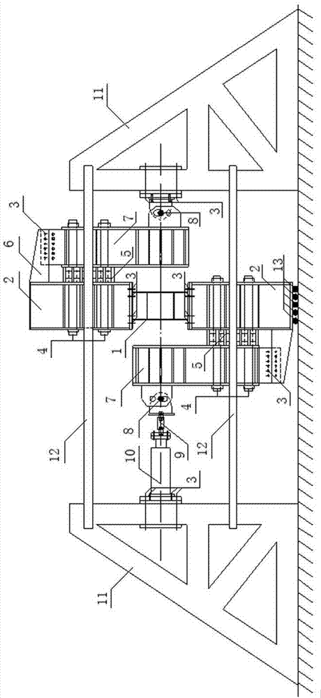
[0007] Such as figure 1 As shown, the technical solution adopted by the present invention to solve this technical problem is: arrange the entire loading device symmetrically with respect to the center of the shear-type energy-dissipating beam section, so as to ensure that the shear-type energy-dissipating beam section is subjected to pure shear force. The shear-type energy-dissipating beam section and the frame beam are designed separately, and the shear-type energy-dissipating beam section and the frame beam are connected by high-strength bolts, so that the independent loading of the shear-type energy-dissipating beam section can be realized, and shearing beam sections of different specifications can be replaced. Type energy-dissipating beam segment specimens.

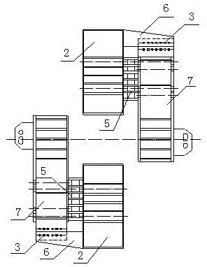
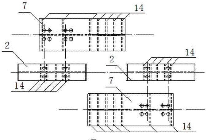
[0008] Such as figure 1 , figure 2 , image 3 As shown, the shear-type energy-dissipating beam section is subjected to pure shear test loading device. The whole test device is divided into four parts: the first pa...


PUM

PropertyMeasurementUnit
thicknessaaaaaaaaaa
pore sizeaaaaaaaaaa

Abstract

The invention relates to a testing and loading device for pure shear on a shear type link beam. The whole testing device comprises a loading frame part, an active loading part, a passive loading part and a shear type link beam part, wherein a loading frame is formed by connecting loading beams and framework beams; the framework beams and the loading beams are connected by high-strength bolts, high-strength pull rods, box type cushion blocks and connecting plates; the active loading part consists of a high-strength bolt left hinge support base, a sensor, a pull and press jack and a left triangular counterforce frame, the left hinge support base is connected with the sensor through a screw rod, the sensor is connected with the pull and press jack through a screw rod, and the pull and press jack is fixedly arranged on the left triangular counterforce bracket through cushion plates and high-strength bolts; the passive loading part consists of a right hinge support base and a right triangular counterforce bracket, and the right hinge support base is fixedly arranged on the right triangular counterforce bracket through cushion plates and high-strength bolts; the shear type link beam can be independently loaded, so that the shear type link beam can endure pure shear.

Description

technical field [0001] The invention relates to the technical field of test loading devices, in particular to the test loading technology for a shear-type energy-dissipating beam segment subjected to pure shear force. Background technique [0002] In the existing loading test devices for shear-type energy-dissipating beam sections, the shear-type energy-dissipating beam section is loaded as a part of the frame beam. The disadvantages are: (1) Since it is not loaded independently, this The method cannot obtain the mechanical performance of the real shear-type energy-dissipating beam section; (2) After the shear-type energy-dissipating beam section is damaged, it is necessary to replace the entire frame beam and the shear-type energy-dissipating beam section when testing again , time-consuming and uneconomical; (3) The stress state of the shear-type energy-dissipating beam segment in pure shear cannot be realized, and the mechanical performance of the shear-type energy-dissipa...

Claims


Application Information

Patent Timeline
Patent Type & Authority Applications(China)
IPC IPC(8): G01N3/02G01N3/24
CPCG01N3/02G01N3/24
Inventor 殷占忠李锦铭赵帅鹏董龙光安树桢张宪栋张晓博潘超超孙向阳方顺中
Owner LANZHOU UNIVERSITY OF TECHNOLOGY
Why Eureka
Try Eureka