Electron beam moire fringe generation apparatus and electron optical imaging system

A technology for moiré fringes and generating devices, which is applied to electrode devices and related components, cathode ray tubes/electron beam tubes, circuits, etc., can solve the time delay of moire fringe images, and the shape of moiré fringes will change, etc. question

Inactive Publication Date: 2017-12-19
SHENZHEN UNIV
View PDF1 Cites 5 Cited by
  • Summary
  • Abstract
  • Description
  • Claims
  • Application Information

AI Technical Summary

Problems solved by technology

Therefore, the image of the electron beam moiré fringe is not generated simultaneously, but the moiré fringe formed by combining multiple scanned images, and there is a delay in time
In addition, the moire fringes produced by this structure are also affected by the magnification, and the shape of the moiré fringes observed under different magnifications will change
Although the method used in the second scheme does not use the raster scanning of the electron beam to generate moiré fringes, and the moiré fringes will not be affected by the magnification, it still uses this scanning method for imaging, so its moiré The fringe image also has delay in time

Method used


Image

  • Electron beam moire fringe generation apparatus and electron optical imaging system
  • Electron beam moire fringe generation apparatus and electron optical imaging system
  • Electron beam moire fringe generation apparatus and electron optical imaging system

Examples


Embodiment

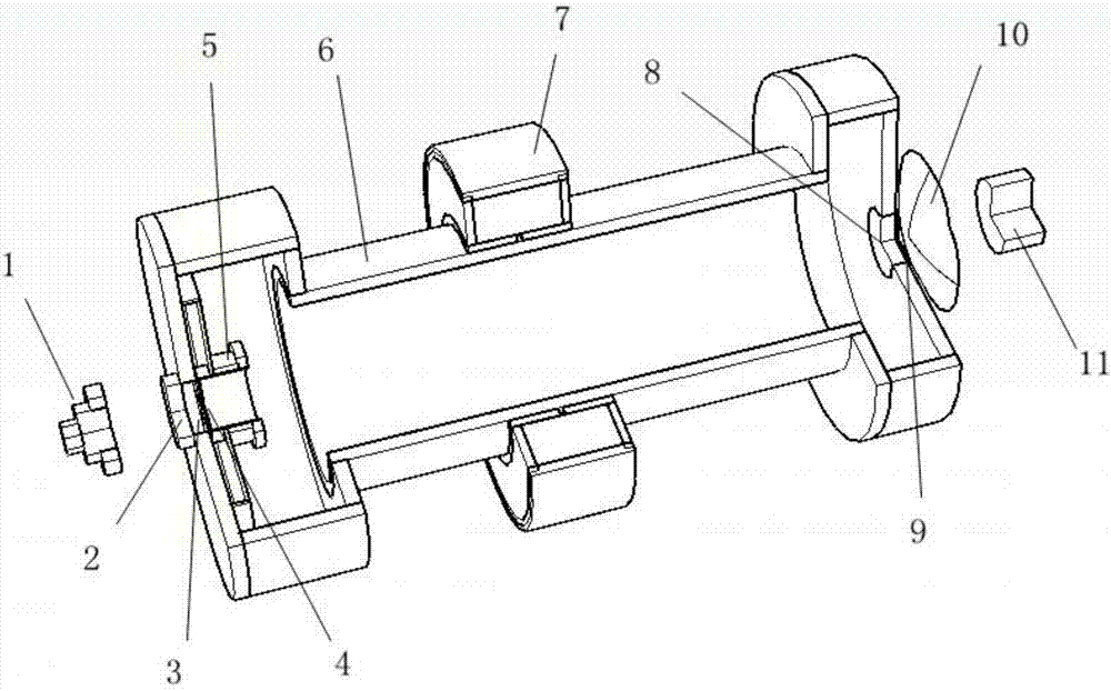
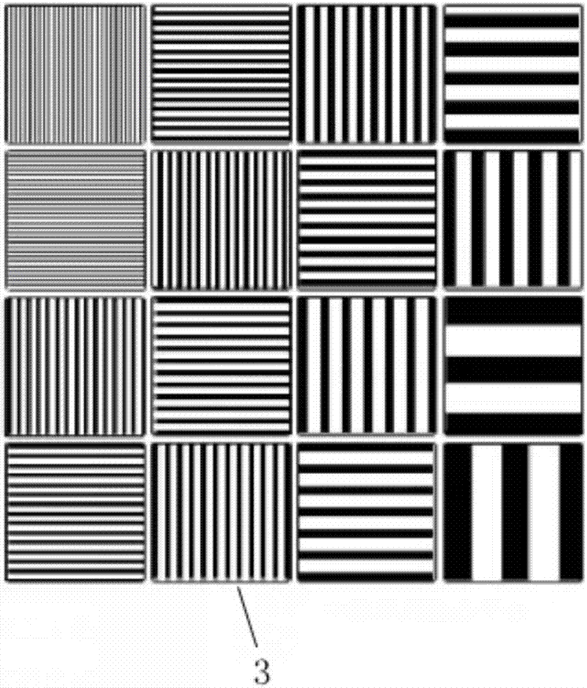
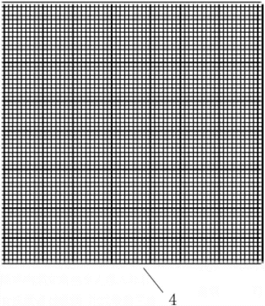
[0038] Please also refer to figure 1 , figure 2 , image 3 , the present embodiment provides an electron beam Moiré fringe generating device, including an excitation light source 1, a light transmission window 2, a photocathode 3, an anode grid 4, a tube shell 6, a frame-changing tube 8, and a fluorescent screen 9.

[0039]Wherein, the excitation light source 1 is used to excite the photocathode 3 with photons to generate electrons. As a preferred excitation light source 1, the excitation light source 1 in this embodiment is an ultraviolet light source. As another preferred excitation light source 1, the excitation light source 1 in this embodiment is an X-ray light source.

[0040] In this embodiment, the tube shell 6 is a metal structure, and its interior is a vacuum environment, which is used to form electron drift channels or drift regions.

[0041] Preferably, the shell 6 is grounded.

[0042] The excitation light source 1 is arranged outside the first end of the tu...


PUM


Abstract

The invention provides an electron beam moire fringe generation apparatus and an electron optical imaging system. The electron beam moire fringe generation apparatus comprises an excitation light source, a light-transmitting window, a photoelectric negative electrode, a positive electrode grid mesh, a tube shell, a framing image converter tube and a fluorescent screen; strip-shaped grooves are arranged on the surface of the photoelectric negative electrode for generating first electronic optical grating; the mesh number of the positive electrode grid mesh is matched with the space frequency of the grooves; and the positive electrode grid mesh is arranged close to the photoelectric negative electrode and used for generating second electronic optical grating and forming electron beam moire fringe under the effects of the first electronic optical grating and the second electronic optical grating. By virtue of the electron beam moire fringe generation apparatus provided by the invention, moire fringe can be generated under the interaction of the photoelectric negative electrode and the positive electrode grid mesh directly, without needing scanning time, so that efficiency is improved.

Description

technical field [0001] The invention relates to the technical field of electronic imaging, in particular to an electron beam moiré fringe generating device and an electron light imaging system. Background technique [0002] As an optical phenomenon, Moiré fringes are often used in fields such as high-order fringe elimination, contour line measurement, concave-convex judgment, and medical diagnosis. In recent years, Moiré fringes in the field of optics have been widely used, but the research and application of Moiré fringes in the field of electron beams is rare. [0003] At present, the most representative electron beam Moiré fringe generation devices include the following two types: the first one is to make scribed lines on the brass sample to form an electron grating, which is formed by scanning the scribed lines on the sample and the electron beam raster of the scanning electron microscope. Electron beam moiré fringes are observed; the second method uses photolithography...

Claims


Application Information

Patent Timeline
IPC IPC(8): H01J29/02H01J29/04H01J29/18H01J29/64
CPCH01J29/02H01J29/04H01J29/18H01J29/64
Inventor 刘进元蔡厚智雷云飞
Owner SHENZHEN UNIV
Why Eureka
Try Eureka